 Tel:
Tel:  Email:
  WhatsApp:
 Description
Key Technical Specifications
| Parameter | Specification |
|---|---|
| Slots | 8 (for Field Control I/O modules) |
| Mounting | DIN Rail (35mm) or Panel Mount (via brackets) |
| Dimensions | Approx. 240mm W x 120mm H x 75mm D (varies slightly by config) |
| Power Input | 24V DC (for module logic/power distribution via backplane) |
| Current Capacity | Depends on power supply module used; typically up to 2A per slot shared |
| Communication | Passive backplane; requires Bus Interface Unit (BIU) in Slot 1 or external |
| Terminal Blocks | Sold separately (e.g., IC670TBM001 for discrete, IC670TBM002 for analog) |
| Operating Temp | 0°C to 60°C (32°F to 140°F) |
| Storage Temp | -40°C to 85°C |
| Humidity | 5% to 95% Non-condensing |
| Certifications | UL, cUL, CE |
| Weight | Approx. 0.5 kg (without modules) |
| Material | High-impact plastic, flame retardant |
Product Introduction
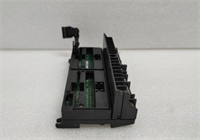
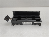
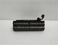
The GE IC670CHS001E is a robust 8-slot base unit designed for the GE Field Control distributed I/O system. It provides a compact and modular solution for mounting up to eight I/O modules in harsh industrial environments. The chassis features an integrated backplane that distributes power and data signals between the modules and the Bus Interface Unit (BIU).This unit is commonly used in applications requiring distributed control, such as packaging machines, conveyor systems, and utility monitoring. The “-E” revision ensures compatibility with the full range of legacy Field Control modules (discrete, analog, thermocouple, etc.). Note that this chassis does not contain intelligence; it must be paired with a BIU (often mounted in the first slot or adjacent) to connect to Profibus, DeviceNet, Ethernet/IP, or Genius networks. Proper termination and DIN rail mounting are critical for vibration resistance.
Installation & Configuration Guide
Preparation (10 min)
Select a location with adequate ventilation and access. Ensure the 35mm DIN rail is securely mounted and grounded. Gather the required I/O modules, terminal blocks, and the Bus Interface Unit (BIU). Verify the 24V DC power supply capacity matches the total load of the planned modules. Have a screwdriver and wire strippers ready.Mounting the Chassis (5 min)
Snap the IC670CHS001E onto the DIN rail by hooking the top edge and pressing the bottom until the locking clips engage with an audible click. For panel mounting, attach the optional bracket kit (if available) and secure with screws. Ensure the chassis is level and stable.Installing Modules (10 min)
Insert the Bus Interface Unit (BIU) into Slot 1 (or the designated communication slot). Insert the remaining I/O modules into slots 2–8. Push each module firmly until it seats against the backplane connector. Secure each module with the retaining screws or clips provided. Attach the appropriate terminal blocks to the front of each module; they usually snap or screw into place.Wiring & Power-Up (10 min)
Connect the 24V DC power to the power input terminals (usually on the BIU or a dedicated power module if used). Wire the field devices to the terminal blocks according to the wiring diagram. Connect the network cable to the BIU. Double-check all polarity connections. Apply power. Observe the LEDs on the BIU and I/O modules; status lights should indicate normal operation (typically green steady or flashing). Use the PLC software to verify I/O mapping and force tests.
Troubleshooting Quick Reference
| Symptom | Probability | Action |
|---|---|---|
| No Power to Modules | High | Check 24V DC input voltage and polarity. Verify fuse/breaker status. |
| BIU Fault LED Red | High | Network configuration error or baud rate mismatch. Check PLC config and cabling. |
| Specific Module Fault | Medium | Module failure or wiring short. Swap module with a known good one to isolate. |
| Intermittent Comm Loss | Medium | Loose DIN rail mount or poor network termination. Tighten rail clips; check terminators. |
| Terminal Block Not Seating | Low | Bent pins on module or broken clip. Inspect visually; replace damaged parts. |
Dimensions, Mounting & Wiring Notes
- Dimensions: ~240mm Width (8 slots) x ~120mm Height x ~75mm Depth.
- Mounting: Standard 35mm DIN Rail (Top-hat). Panel mount kits may be required for flush installation.
- Terminal Notes: Terminal blocks are model-specific (e.g., spring clamp vs. screw terminal). Ensure the block matches the module type (Discrete vs. Analog). Wire gauge: 14–24 AWG. Torque screw terminals to 0.5 Nm. Keep power and signal wires separated where possible to reduce noise.
IC670CHS001E GE
FAQ
Q: Does the IC670CHS001E come with power supply?
A: No, it is a passive chassis. You need a 24V DC power supply connected to the system (usually via the Bus Interface Unit or a dedicated power module inserted into the chassis).Q: What modules fit in this chassis?
A: Any GE Field Control I/O module (IC670 series) fits, including discrete, analog, high-speed counter, and thermocouple modules. It is not compatible with VersaMax plug-in cartridges directly without the specific carrier, but shares the ecosystem.Q: Can I use fewer than 8 slots?
A: Yes. You can populate only the slots you need. Empty slots do not require filler plates but keeping them covered helps prevent dust ingress.Q: What is the difference between CHS001 and CHS002?
A: Often denotes the number of slots (e.g., 8 vs 12) or minor mechanical updates. The CHS001 is typically the 8-slot version. Always verify physical dimensions before retrofitting into tight enclosures.Q: How do I replace a faulty module?
A: Power down if possible (though some systems support hot-swap, it’s risky). Unlatch the terminal block (if removable), unscrew/unclip the module, slide it out, and insert the new one. Reattach the terminal block and restore power.
Quality Transparency Strategy (SOP)
1. Incoming Inspection
We validate the model number and “-E” revision. Anti-counterfeit checks include inspecting the plastic molding quality, label adhesion, and font consistency. Physical inspection focuses on the integrity of the DIN rail clips (cracks are common in old units), backplane pin condition (bent pins prevent module seating), and mounting screw holes. We ensure no internal debris exists.2. Live Functional Testing
Since this is a passive chassis, testing involves installing a known-good Bus Interface Unit and a variety of I/O modules (discrete and analog). We verify that power distributes correctly to all 8 slots by measuring voltage at each slot’s test points. We simulate data traffic through the backplane by toggling inputs and reading outputs on every slot. A 24-hour vibration test (simulated) ensures modules stay seated. A report confirms backplane continuity and power stability.3. Electrical Testing
Continuity checks are performed on the backplane traces for power (24V, 0V) and data lines. Insulation resistance is measured between power rails and the chassis frame. We verify there are no short circuits between adjacent slot pins.4. Mechanical Verification
We test the locking mechanism of the DIN rail clips to ensure they hold firm under tension. We verify that terminal blocks snap on/off smoothly without excessive force. Photos are taken of any cosmetic wear (scratches, discoloration) for disclosure.5. Final QC & Packaging
A senior technician signs the QC checklist. The chassis is cleaned, sealed in an anti-static bag (if electronic components are exposed, though mostly plastic), and packed in a double-wall carton with foam corner protectors to prevent rail clip breakage during shipping. A “QC Passed” label is applied.
Function verified under test conditions.
Technical Pitfall Guide
DIN Rail Clip Failure
Older plastic clips can become brittle and snap during installation or due to vibration, causing the whole station to detach. Scenario: A vibrating conveyor caused an unsecured chassis to loosen, breaking data connections. Rule: Inspect clips closely; if cracked, replace the chassis or use supplementary mounting brackets/screws.Backplane Pin Damage
Forcing a module into a misaligned slot can bend the delicate backplane pins, leading to open circuits for power or data. Warning: Always align modules carefully before pushing. If resistance is felt, stop and inspect. Bent pins are very difficult to repair reliably.Power Distribution Limits
While the chassis distributes power, the total current draw of all modules cannot exceed the capacity of the input power source or the internal bus bars. Check: Calculate the total current consumption of all installed modules. Ensure the 24V supply has sufficient headroom (min 20%).Terminal Block Mismatch
Using a discrete terminal block on an analog module (or vice versa) can damage the module or provide incorrect wiring density. Tip: Always match the terminal block part number exactly to the module type. They often look similar but have different internal shunting or pin assignments.Grounding Issues
Poor grounding of the DIN rail can lead to noise issues, especially for analog modules. Best Practice: Ensure the DIN rail is bonded to the cabinet ground with a low-impedance strap. Ground the shield of field cables at the entry point to the cabinet.