 Tel:
Tel:  Email:
  WhatsApp:
 Description
Key Technical Specifications
| Parameter | Specification |
|---|---|
| Board Function | TCQA (Analog I/O Signal Conditioning) |
| Input Signals | LVDT, Thermocouple, 4-20mA, Vibration, Pulse |
| Output Signals | Servo Valve Drive, Relay Driver, 4-20mA Output |
| Connectors | 2PL (Power), 3PL (Data Bus), JE (Gen/Line Sig) |
| Configuration | Jumpers J1, J2 (mA Output); J5, J6 (Current Range) |
| Current Range | Selectable 20 mA or 200 mA via Jumpers |
| Data Bus | Corebus interface via 3PL connector |
| Mounting | Mark V I/O Core (R1, R2, R3) |
| Test Port | J7 (RS232 for Card Test) |
| Oscillator | J8 (Start Oscillator Jumper) |
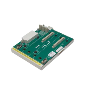
Product Introduction
In the world of GE Mark V turbine controls, the “Core” is the brain, but the DS200SI0CG1AEA (TCQA board) is the nervous system. I’ve spent too many nights debugging “bad feedback” alarms only to find out this board was drifting or misconfigured. It handles the dirty work of scaling raw signals—like the voltage from an LVDT or the millivolts from a thermocouple—into something the processor can actually understand. Without it, your turbine is flying blind.This isn’t a “plug-and-play” part if you aren’t careful. It lives in the I/O Core (R1, R2, R3) and manages everything from compressor stall detection to fuel flow pressure. The beauty of this board is its density; it packs 4-20mA conditioning, servo valve drives, and thermocouple inputs onto one card. However, it’s sensitive. If you mess up the jumper settings on J5 or J6, you’ll send the wrong current to your servo valve, which can cause the fuel nozzle to stick. Treat this board with respect, and it’ll keep your turbine running smooth.
Quality SOP & Tech Pitfalls (The Reality Check)
The Lab Report (SOP)
We don’t just ship cardboard boxes.
- Visual Inspection: We check the pin connectors for straightness—bent pins on the 3PL connector are a common shipping casualty.
- Jumper Verification: We verify the factory default jumper settings against the OEM manual to ensure they match standard TCQA configs.
- Live Test: We run a signal injection test on the 4-20mA inputs and verify the scaling output on the data bus using a Mark V simulator.
- Connector Check: We inspect the JE and JF connectors for corrosion or loose crimps.
- Packing: Static-shielded bag with heavy-duty foam blocking to prevent connector damage.
The Engineer’s Warning (Pitfalls)
- The Jumper Trap: This board has a specific set of jumpers (J1, J2, J5, J6) that define the current output range (20mA vs 200mA). I once saw a technician swap this board without checking J5/J6. The new board was set to 200mA, but the old one was 20mA. The result? It overdriven the I/P converter and caused a fuel spike during startup. Always photograph the jumper settings on your old board before you pull it.
- Ground Loops: The TCQA board is notorious for picking up noise if the ground strap on the I/O Core isn’t tight. If you see erratic LVDT readings after the swap, check your chassis grounding first. Don’t blame the card until you’ve checked the ground.
Installation & Configuration Guide
Phase 1: Pre-Installation (Safety First)
⚠️ Lockout/Tagout (LOTO): De-energize the Mark V panel. Wait for the DC bus capacitors to discharge (check with a multimeter).
⚠️ Documentation: Take a high-resolution photo of the existing board’s jumpers (J1, J2, J5, J6, J7, J8). This is non-negotiable.
Phase 2: Removal
- Disconnect the external cables from the JE, JF, and JG connectors. Label them “Top,” “Middle,” “Bottom” if they aren’t already marked.
- Unscrew the captive screws holding the board to the I/O Core chassis.
- Slide the board out gently. Do not wiggle it excessively; the backplane pins are fragile.
Phase 3: Installation
- Configuration: Adjust the jumpers on the new DS200SI0CG1AEA to match your photo exactly.
- Align the board with the card guides and slide it in. Ensure the 3PL data bus connector seats firmly.
- Tighten the captive screws. Reconnect the external cables (JE, JF, JG).
Phase 4: Power-On & Testing
- Apply control power.
- Check the LED indicators (if equipped) or use the handheld programmer to check for “I/O Faults.”
- Verify LVDT feedback values in the software. If they read “0” or “Rail High,” power down and check your JF connector seating.
Compatible Replacement Models
| Compatibility Tier | Model Number | Notes |
|---|---|---|
| ✅ Drop-in Replacement | DS200SI0CG1AEA | Exact match. Verify jumper settings. |
| ✅ Direct Equivalent | DS200SI0CG1AEB | Later revision. Generally backward compatible, but check manual. |
| ⚠️ Hardware Mod | DS200TCQAG1… | Different form factor. Requires chassis modification. |
| ❌ Incompatible | DS200STCAG1… | This is a Servo Terminal board, not an Analog I/O board. |
Frequently Asked Questions (FAQ)
Q: What does the “TCQA” acronym mean?
A: It stands for “Terminal Analog I/O.” It basically means this board conditions the analog signals (voltage, current, temperature) coming from the terminal boards (TBQA, TBQC) before sending them to the processor.Q: Can I swap this board while the turbine is running?
A: No. This board handles critical control signals like fuel flow and servo valve positioning. Pulling it live will cause a massive control upset and likely trip the turbine. You need a shutdown.Q: My new board has different jumper settings. Should I change them?
A: Yes. You must match the jumpers (J1, J2, J5, J6) to your old board. The “AEA” suffix defines the hardware, but the jumpers define how it interacts with your specific turbine application (Frame 5 vs. Frame 9, for example).Q: What is the J7 connector used for?
A: That’s the RS232 test port. It’s used for bench testing the card with a PC. You generally won’t touch this during installation unless you are doing advanced diagnostics with a laptop.Q: Why are my LVDT readings fluctuating?
A: If the board is seated correctly, check the JF connector. It carries the LVDT signals. If that cable is loose or the shielding is damaged, you’ll get noise. Also, verify that the TBQA terminal board (where the LVDT plugs in) isn’t the culprit.Q: Does this board handle thermocouples?
A: Yes. The TCQA board processes the thermocouple inputs (via the TBQA terminal board) and handles the Cold Junction Compensation. If your exhaust temps look weird, check the JAR/S/T connectors on the terminal board side.