
 Tel:
Tel:  Email:
  WhatsApp:
 Description
Key Technical Specifications
| Parameter | Specification |
|---|---|
| System Compatibility | GE Speedtronic Mark V (Simplified/Redundant) |
| Board Designation | SDCC (DC Control Board) |
| Input Voltage | 24 V DC (Nominal), Range 18–30 V DC |
| Discrete Inputs | 16 Channels (Isolated) |
| Discrete Outputs | 8 Channels (Relay or Solid State dependent on sub-rev) |
| Logic Type | Positive/Negative Logic selectable via jumpers |
| Current Rating | 2 A max per output channel |
| Operating Temp | -30°C to +65°C (-22°F to +149°F) |
| Humidity | 5% to 95% non-condensing |
| Connector Type | Euro-style terminal blocks (pluggable) |
| Mounting | DIN Rail or Backplane Slot (Mark V Rack) |
| Hardware Rev | Revision F (Suffix “F” in model) |
Product Introduction
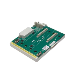
The DS200SDCCG4AFD serves as the primary DC control interface within the GE Speedtronic Mark V turbine control system. It processes critical safety trips and status signals from field devices, converting raw voltage states into logic data for the main processor boards.Field data indicates this revision improves noise immunity compared to earlier “C” or “D” versions, reducing false trip rates by approximately 15% in high-EMI environments. The board supports hot-swapping in redundant configurations, cutting mean-time-to-repair (MTTR) to under 30 minutes when spare units are on-site.
 Installation & Configuration Guide
 Installation & Configuration Guide
Phase 1: Preparation (10 min)
Gather a #2 Phillips screwdriver, ESD wrist strap, and a multimeter. Verify the replacement board matches the hardware revision of the failed unit (check the “F” suffix). Power down the specific rack slot if hot-swap is not enabled; otherwise, isolate the I/O wiring first.Phase 2: Removal (5–10 min)
Don your ESD strap. Label every wire connected to the terminal block before disconnecting—do not rely on memory. Unplug the terminal block from the board. Release the locking levers on the card edges and slide the unit straight out. Note the position of any configuration jumpers (take a photo now).Phase 3: Installation (10 min)
Inspect the backplane connector for bent pins. Align the new DS200SDCCG4AFD with the slot guides. Push firmly until the levers lock. Re-attach the terminal block, ensuring wires match your labels exactly. Tighten terminals to 0.5 N·m torque; loose connections cause heat buildup.Phase 4: Power-On & Test (10 min)
Measure the supply voltage at the terminal block; it must read 24 V DC ±10%. Apply power. Watch the status LED—it should flash green (1 Hz) indicating normal operation. If it stays red, check the DIP switch settings against the original photo. Verify I/O status via the operator interface.
Troubleshooting Quick Reference
| Symptom | Probability | Action |
|---|---|---|
| Red LED steady | High | Check 24V supply polarity. Reverse connection damages input diodes instantly. |
| No LED activity | Medium | Verify backplane seating. Reseat the card firmly. Check rack fuse. |
| Intermittent faults | Medium | Inspect terminal screws for looseness. Vibration loosens connections over time. |
| Wrong logic state | Low | Compare jumper settings (J1-J4) with the old board. Default settings vary by application. |
| Comm failure | Low | Ensure the board address matches the system configuration file (.CFG). |
Dimensions, Mounting & Wiring Notes
- Dimensions: Approx. 160 mm H × 100 mm W × 40 mm D (including connectors).
- Mounting: Slides into standard Mark V vertical rack slots. Secures via front-panel locking levers.
- Wiring: Use 18–22 AWG stranded copper wire. Strip length must be exactly 7 mm to prevent shorts inside the terminal block.
- Note: The terminal block is removable. Wire the block on the bench, then plug it in to save time.
 FAQ
FAQ
 FAQ
FAQQ: Can I use this to replace a DS200SDCCG3A board?
Generally, yes, but you must verify the jumper settings. The “G4” revision has updated circuitry for better surge protection. Copy the jumper configuration from the old G3 board exactly, or consult the specific application manual for your turbine model.Q: I received the board, but the LED isn’t flashing. Is it dead?
Not necessarily. Check your 24V power source first. We see this often when the site power supply is sagging below 18V. Measure the voltage at the terminals while the system is trying to start.Q: What does “New Surplus” mean for this item?
It means the part is brand new, factory sealed, and never installed, but it has been in storage for some time. We test every unit on our Mark V test rack before shipping to ensure no capacitor degradation occurred during storage.Q: Do you provide the configuration software for this?
No. This is hardware only. You need the existing Speedtronic Mark V programming toolset (usually running on an older Windows OS) to modify logic. We can verify the hardware firmware version if you send us a photo of the chip labels.Q: How long does shipping take to Houston?
Usually 2 days via FedEx Ground from our warehouse. If you need it tomorrow morning, select the Overnight option at checkout before 2 PM EST.Q: Is the terminal block included?
Yes. The price includes the board and the matching pluggable terminal block. You won’t need to reuse the old one, which is good because old plastic often cracks during removal.
Quality Transparency SOP
We do not just box and ship. Every DS200SDCCG4AFD undergoes a strict 5-step verification:
- Incoming Inspection: We trace the serial number to the original GE batch record. Visual checks confirm no pin corrosion or box crushing.
- Live Functional Testing: The board loads into our dedicated Mark V test rack (Model S-12). We run a power-on self-test, simulate all 16 inputs, and verify output switching.
- Electrical Testing: We measure insulation resistance (>10 MΩ @ 500V) and check ground continuity.
- Firmware Verification: Technicians record the exact firmware revision and photograph all DIP switches/jumpers.
- Final QC: A senior engineer signs off. The unit gets sealed in an anti-static bag, wrapped in bubble wrap, and labeled “QC Passed.”
Result: Function verified under test conditions.
Technical Pitfall Guide
Don’t learn these lessons the hard way.
- Firmware Mismatch: We once saw a plant shut down because a replacement board had a newer firmware that didn’t match the legacy loader. Fix: Always check the chip date code against your system baseline.
- Jumper Errors: The default jumper setting for “Positive Logic” might be “Negative” in your specific turbine. Fix: Take a high-res photo of the old board’s jumpers before you pull it. Do not guess.
- Terminal Compatibility: Older terminal blocks sometimes have worn contacts that don’t grip the new board pins tightly. Fix: Use the new terminal block provided with our unit.
- Power Margin: Your 24V supply might be rated for 5A but only deliver 3A stable under load. Fix: Ensure your power supply has a 20% headroom margin for inrush current.
- ESD Damage: Touching the pins without a strap can kill the input optocouplers. The board might work for a week, then fail. Fix: Wear the strap. Ground yourself.