
 Tel:
Tel:  Email:
  WhatsApp:
 Description
Key Technical Specifications (For Spare Part Verification)
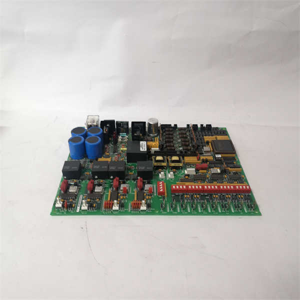
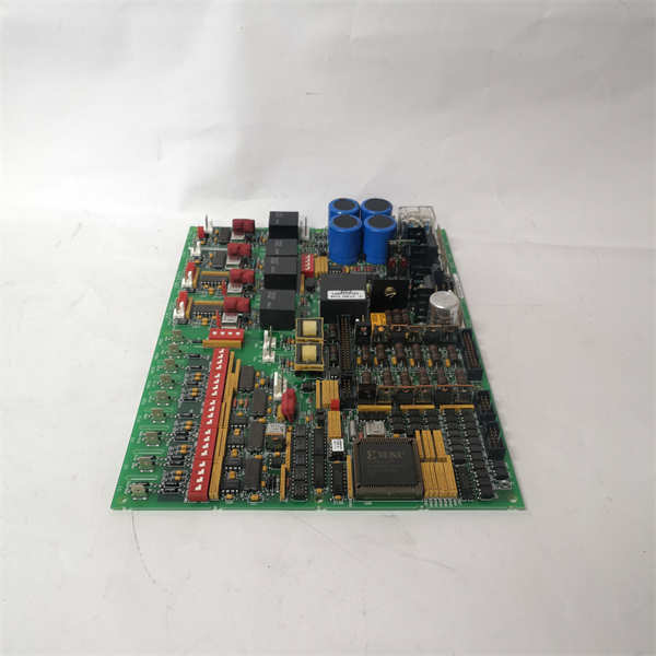
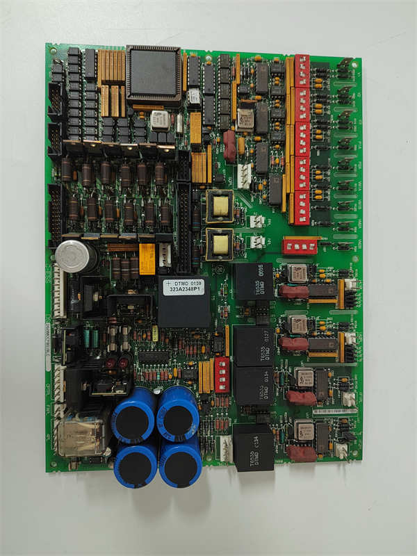
- Model: DS200DCFBG1BLC
- Manufacturer: General Electric (GE Power)
- System Platform: Speedtronic Mark V (used on Frame 5, 6, 7, and 9 gas turbines)
- Board Revision: G1BLC (revision code critical for compatibility)
- Function: Aggregates analog/digital I/O from terminal boards and interfaces with PTBA/PTBS via VME backplane
- Connectors: Multiple ribbon cable headers for TBAs (analog), TBHs (digital), and CTBA (communications)
- Diagnostic LEDs: Multiple status indicators for power, communication, and fault conditions
- Firmware: Loaded via PROM; revision must match system software (e.g., CSP or Toolbox version)
- Mounting: Vertical slot in core control chassis (typically Slot 3 or 4 in a 6-slot rack)
- Redundancy: Operates in TMR (Triple Modular Redundant) configuration—three identical DCFBs required per system
- Auxiliary Power: Powered via backplane; requires stable +5 V, ±15 V rails
System Role and Impact of Failure
The DS200DCFBG1BLC is a foundational hardware component in the GE Mark V control architecture. It acts as the primary data concentrator for field signals—receiving analog inputs (e.g., exhaust temperature, vibration, pressure) from TBA terminal boards and digital I/O (e.g., valve feedback, breaker status) from TBH boards—then relaying this data to the three redundant control processors (PTBAs). It also transmits output commands to servo-valve drivers and trip solenoids. In a TMR system, all three DCFB boards must agree on signal values; a single failed or mismatched unit can trigger a “voting mismatch,” forcing the turbine into a controlled shutdown or preventing startup. Given its central role, a faulty DCFB can render an entire gas turbine inoperable, with outage costs often exceeding hundreds of thousands of dollars per day in lost generation or production.
Reliability Analysis and Common Failure Modes
Despite robust industrial design, the DS200DCFBG1BLC is vulnerable to several age- and environment-related failure mechanisms:
- Connector fatigue: Repeated thermal cycling causes expansion/contraction of ribbon cable headers, leading to intermittent contact or broken pins—especially on high-vibration sites.
- PROM corruption or obsolescence: The onboard firmware PROM may degrade over time, or newer system software may reject older revisions, causing boot failures.
- Power rail instability: Degraded capacitors on the board’s local regulation circuits can cause voltage droop under load, leading to erratic behavior or watchdog resets.
- Electrostatic discharge (ESD) damage: Improper handling during maintenance can damage CMOS logic or analog input buffers without immediate symptoms, causing latent failures.
A key weakness is the lack of field-replaceable subcomponents; the board is treated as a single line-replaceable unit (LRU). Additionally, counterfeit or improperly refurbished units may pass basic power-on tests but fail under real-time I/O stress.
Preventive measures include:
- Regular inspection of ribbon cable seating and connector integrity
- Verifying board revision against the system’s CSP (Control Sequence Program) version
- Maintaining proper cabinet cooling to reduce thermal stress
- Storing spares in ESD-safe, dry environments with static shielding
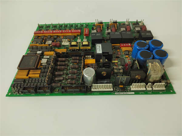
GE DS200DCFBG1BLC
Lifecycle Status and Migration Strategy
GE discontinued the DS200DCFBG1BLC following the end of Mark V production. While limited repair services exist through third parties, no new units are manufactured, and official GE support is restricted to legacy service contracts. Continuing to operate Mark V systems carries escalating risk: spare availability is declining, technical expertise is retiring, and cybersecurity vulnerabilities cannot be patched.
Short-term strategies include:
- Securing multiple tested spares with matching revisions
- Implementing strict ESD and handling protocols during maintenance
- Performing annual functional verification under simulated load
For long-term viability, migration to Mark VIe is the industry-standard path. This involves replacing the entire control core—including DCFB, PTBA, and terminal boards—with a modern, Ethernet-based platform featuring enhanced diagnostics, remote access, and compliance with current grid codes. GE offers conversion kits and engineering services to streamline the transition, though the project typically requires a planned outage and re-commissioning of all control loops. Facilities should initiate feasibility studies now to avoid forced outages due to sudden hardware unavailability.


