

 Tel:
Tel:  Email:
  WhatsApp:
 Description
Key Technical Specifications (For Spare Parts Verification)
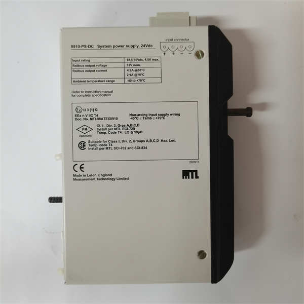
- Product Model: 8910-PS-DC
- Manufacturer: GE Multilin (General Electric)
- System Platform: Accessory power module for Multilin S-series and G-series relays
- Input Voltage: 24–250 VDC (wide-range DC input typical for substation battery systems)
- Output Voltage: Regulated +5 VDC and ±15 VDC (for relay internal logic and analog circuits)
- Output Current: Designed to power one standard Multilin relay (typically ≤2 A total)
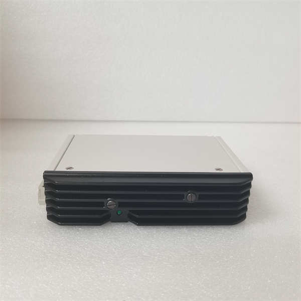
- Mounting: DIN rail or panel mount, often installed adjacent to the relay in a protection cubicle
- Isolation: Reinforced isolation between input and output per IEC 61010
- Indicators: LED status indicator for power-on (if equipped)
- Operating Temperature: -25°C to +70°C
- Certifications: CSA, UL, CE (depending on production date)
System Role and Downtime Impact
The 8910-PS-DC is commonly found in utility substations, industrial switchgear, and motor control centers where GE Multilin relays are deployed without built-in wide-range power supplies. It converts station battery DC (e.g., 48 V, 125 V, or 250 VDC) into the precise low-voltage rails required by older relay models that lack universal power inputs. This module is not merely auxiliary—it is essential. If it fails due to component degradation or overvoltage stress, the connected relay loses all power, rendering protection functions (overcurrent, differential, distance, etc.) completely inoperative. Unlike modern relays with dual power inputs or self-monitoring, this external supply offers no alarm output or health indication. Its failure may go unnoticed until a fault occurs, at which point the system lacks protection—posing serious safety, equipment, and regulatory compliance risks. In radial distribution systems or critical motor applications, such a blind spot can lead to cascading outages or equipment destruction.
Reliability Analysis and Common Failure Modes
The 8910-PS-DC is prone to several age-related failure mechanisms inherent in early-generation DC/DC converters. The most common issue is failure of electrolytic capacitors in the output filter stage, which dry out over time, causing increased ripple voltage, output droop under load, or complete shutdown. Semiconductor switches (MOSFETs) and control ICs can degrade due to thermal cycling, especially in high-ambient environments without adequate ventilation. The unit’s compact design offers minimal thermal margin, accelerating component wear. A key vulnerability is its lack of remote monitoring—there is no “power fail” contact or communication interface to alert operators of degradation. For preventive maintenance, technicians should annually measure output voltages under load, inspect for bulging or leaking capacitors, verify secure terminal connections, and ensure the unit is not obstructed by dust or adjacent heat sources. Keeping a known-good spare powered in a test panel can help validate readiness before emergency use.
8910-PS-DC GE
Lifecycle Status and Migration Strategy
GE has discontinued the 8910-PS-DC as part of its legacy product phase-out. New units are unavailable through authorized channels, and remaining stock consists of old inventory with unknown storage history—increasing the likelihood of infant mortality upon installation. Continued use introduces unacceptable risk in protection-critical applications. As a short-term workaround, some users install generic industrial DC/DC converters with matching specs, but these often lack the transient immunity and isolation required for substation environments. The sustainable solution is to replace the entire relay system with a modern, self-contained unit. For example, the Multilin™ 489 Motor Management Relay or G60 Generator Protection System (current versions) feature universal 24–250 VAC/VDC power inputs with built-in redundancy and diagnostics—eliminating the need for external supplies. Migration involves removing the 8910-PS-DC and its associated wiring, mounting the new relay directly, and reconfiguring settings via Enervista software. While this requires upfront engineering effort, it significantly reduces long-term lifecycle risk and aligns the system with current IEEE and IEC protection standards. Prioritizing high-impact feeders first ensures optimal risk reduction per investment.


