 Tel:
Tel:  Email:
  WhatsApp:
 Description
Technical Specifications (For Spare Parts Verification)
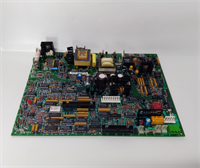
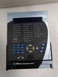
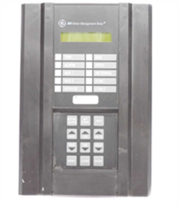
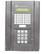
- Product Model: 369-HI-R-0-0-0
- Manufacturer: GE Multilin
- Associated System: Multilin 369 Motor Management Relay Platform
- Current Inputs: 3-phase + ground (5 A or 1 A selectable)
- Special Feature: “HI” option supports extended motor start-up times (up to 60 seconds)
- RTD Inputs: 3 channels (for stator or bearing temperature monitoring)
- Outputs: 6 programmable Form-C relays (trip, alarm, auxiliary)
- Communication: RS-485 (Modbus RTU only – no Ethernet)
- Display: 2-line LCD with keypad navigation
- Power Supply: 24–250 VDC or 88–265 VAC (universal)
- Standards Compliance: IEEE C37.96, IEC 60255
System Role and Downtime Impact
The 369-HI-R-0-0-0 is typically installed as the primary protection device for medium-voltage (2.3–13.8 kV) motors in oil & gas, mining, water treatment, and chemical plants—especially those with high inertia loads like slurry pumps or air compressors that require long acceleration times. Its “HI” (High Inrush) configuration allows the thermal model to accommodate extended starting currents without nuisance tripping, while RTD inputs provide direct stator temperature monitoring. If this relay fails—due to power supply degradation, memory corruption, or output relay welding—the motor loses all intelligent protection. This leaves it vulnerable to burnout from overload, phase imbalance, or locked rotor conditions. In continuous-process facilities, such a failure can trigger an unplanned line stoppage costing tens of thousands of dollars per hour, in addition to potential motor rewind or replacement costs exceeding $ 100,000.
Reliability Analysis and Common Failure Modes
The 369-HI-R-0-0-0, while robust for its era, suffers from predictable aging issues common to early digital relays. The most frequent failure is electrolytic capacitor degradation in the internal switch-mode power supply, leading to voltage instability, spontaneous resets, or complete power loss. A second common issue is relay contact welding on the trip output due to repeated high-current switching during fault clearing, which can either cause failure-to-trip or unintended tripping. Additionally, the non-volatile memory (NVRAM) that stores settings and event logs is prone to data corruption after 15+ years, especially if the onboard lithium battery (typically 3.6 V) depletes.
A key vulnerability is the lack of self-monitoring diagnostics. Unlike modern relays, the 369 cannot report internal health (e.g., power rail status, memory integrity), so faults often go undetected until a real event occurs. Moreover, its Modbus-only communication limits remote verification of settings or event history.
Recommended preventive actions include:
- Annual functional testing using a relay test set (e.g., OMICRON CMC) to verify all protection elements
- Measurement of backup battery voltage; replace if below 3.2 V to prevent setting loss
- Inspection of terminal blocks for overheating signs (discoloration, oxidation)
- Verification of CT saturation margins under fault conditions, as older relays have less robust filtering
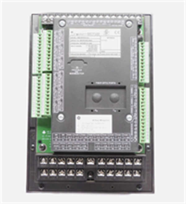
GE 369-HI-R-0-0-0
Lifecycle Status and Migration Strategy
GE ceased production of the 369 series more than 12 years ago, and Baker Hughes no longer provides repair services, calibration, or technical documentation beyond archival PDFs. Continuing to rely on this relay exposes operations to significant risk: unverifiable spare parts, inability to recover settings after failure, and non-compliance with modern arc-flash or cybersecurity standards.
For facilities unable to fund immediate upgrades, two short-term options exist:
- Cold-spare stocking: Acquire and fully test multiple 369-HI-R-0-0-0 units now while inventory remains available.
- Drop-in functional replacement: Install a Multilin 469 or M60 relay in the same panel cutout (with adapter bracket), reusing existing CTs and wiring where possible.
The recommended long-term path is migration to the Multilin M60 or M70, which offer Ethernet (IEC 61850, Modbus TCP), enhanced thermal modeling, waveform capture, and remote access via web interface. Although re-engineering of protection logic and SCADA integration is required, the new platform provides predictive insights (e.g., insulation degradation trends) and reduces lifecycle costs through simplified maintenance. Given the critical role of motor protection in asset integrity, delaying this transition increases both financial and operational exposure.