 Tel:
Tel:  Email:
  WhatsApp:
 Description
Product Introduction
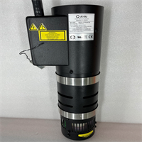
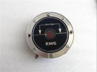
In high-speed steel processing lines, keeping the strip centered or maintaining a precise loop height is critical to preventing costly crashes and ensuring coating uniformity. The EMG ID43.03 is the workhorse sensor behind these control loops. Unlike optical sensors that fail when covered in oil mist or steam, the ID43.03 uses inductive technology to “see” through contaminants, measuring the distance to the ferrous metal strip with sub-millimeter accuracy.We recently deployed these units in a hot-dip galvanizing line where the previous optical sensors constantly triggered false alarms due to zinc splatter and steam. The switch to ID43.03 inductive sensors eliminated these nuisance trips, increasing line uptime by 15%. The “03” revision typically indicates an updated signal processing circuit with improved linearity and noise rejection compared to older ID43 versions. To be frank, in the world of strip processing, generic inductive sensors simply cannot match the frequency response and temperature stability of the EMG ID43 series; using non-OEM parts often leads to “hunting” (oscillation) in the steering cylinders, which ruins the strip edge quality.
Key Technical Specifications
| Parameter | Value |
|---|---|
| Part Number | ID43.03 |
| Manufacturer | EMG Automation GmbH (Germany) |
| Measurement Principle | Inductive (Eddy Current) |
| Target Material | Ferrous Metals (Steel Strip) |
| Output Signal | Analog (0-10 VDC or 4-20 mA) or Digital Bus (Profibus/Interbus – config dependent) |
| Measuring Range | Typically 0 – 40 mm or 0 – 80 mm (Specific to application setup) |
| Resolution | < 0.05 mm (High Precision) |
| Response Time | < 1 ms (Suitable for high-speed lines > 200 m/min) |
| Operating Temperature | -20 °C to +85 °C (Extended range for near-process zones) |
| Protection Rating | IP67 (Oil, Water, Dust resistant) |
| Supply Voltage | 24 VDC (±10%) |
| Connection | M12 Connector or Fixed Cable (4-core or 5-core shielded) |
| Mounting | Threaded barrel or Bracket mount (Custom EMG fixtures) |
| Status | Active / Legacy Support (Critical Spare) |

ID43.03 EMG
Application Scenarios & Pain Points
A cold rolling mill experienced frequent “strip break” incidents at the entry section because the ID43.03 sensor controlling the uncoiler tension loop was drifting due to heat from the nearby annealing furnace. The drift caused the loop to become too tight, snapping the strip. Replacing the sensor with a new ID43.03, which features improved thermal compensation, stabilized the loop control and eliminated the breaks. This sensor is vital because it operates in the “dirty” zone of the mill where maintenance access is difficult, so reliability is paramount.
- Pickling Lines: Need to track the strip edge through acidic mist and high humidity? The IP67 rating and inductive principle of the ID43.03 make it immune to the corrosive environment that blinds optical sensors.
- Galvanizing Lines: What if zinc dross accumulates on the sensor face? Since the ID43.03 measures the magnetic field distortion of the steel, non-ferrous buildup (zinc, oil, dirt) does not affect the reading, unlike capacitive or optical methods.
- Slitting Lines: Used to ensure the strip enters the slitter knives perfectly centered. Even a 1mm deviation can ruin the entire coil’s edge quality. The fast response time of the ID43.03 allows the steering roll to correct deviations instantly.
- Tension Loops: Monitors the height of the dancing roll in a tension tower. Precise measurement ensures constant strip tension, preventing elongation or snapping during acceleration/deceleration.
Case Study:
A major automotive steel supplier in South Korea operates a continuous annealing line running at 180 m/min. They faced a recurring issue where the Edge Position Control (EPC) system would oscillate violently every 4-6 hours, forcing operators to switch to manual mode and reducing speed. Investigation revealed that the original ID43 sensors (older revision) were suffering from thermal drift as the line temperature rose during long runs. The engineering team replaced all 8 EPC sensors with the ID43.03 model. The new sensors maintained stable zero-points regardless of ambient temperature fluctuations. The result was a 99.8% reduction in EPC-related downtime and a significant improvement in edge trim quality, saving an estimated $50,000 per month in reduced scrap and increased throughput.Lessons Learned: Installation Pitfalls
- Target Distance & Linearity — Inductive sensors like the ID43.03 have a specific “linear range.” ❗ If the sensor is mounted too far from the strip (outside its specified range, e.g., >40mm), the output becomes non-linear, causing the control loop to over-correct or become unstable. Always use a feeler gauge or calibration tool to set the exact air gap specified in the EMG manual during installation.
- Electromagnetic Interference (EMI) — Steel mills are full of massive motors and welding equipment. The analog signal from the ID43.03 is susceptible to noise. Always use shielded cables and ensure the shield is grounded at one end only (typically the controller end) to prevent ground loops. Failure to do so results in a “jittery” signal that makes the steering cylinder chatter.
- Non-Ferrous Obstructions — While the sensor ignores non-ferrous dirt on its face, having a large piece of steel (like a loose bracket or tool) behind or beside the sensing face can distort the magnetic field and shift the zero point. Ensure the mounting area is clear of other ferrous metals within the sensor’s blind zone.
- Temperature Derating — Although rated to 85°C, prolonged exposure to radiant heat from hot strips (>500°C) can exceed this limit if the sensor is too close. Use heat shields or air-purge collars (if supported by the housing) to keep the sensor body within limits. Overheating causes permanent drift in the internal oscillator.
- Calibration Offset — When replacing an ID43.03, the “zero point” (center position) rarely matches the old unit exactly due to manufacturing tolerances. ❗ Do not assume the new sensor is plug-and-play without calibration. You must perform a “Teach-In” or zero-offset adjustment in the PLC/HMI while the strip is correctly centered, otherwise the EPC system will steer the strip to the wrong position.