 Tel:
Tel:  Email:
  WhatsApp:
 Description
Key Technical Specifications (For Spare Part Verification)
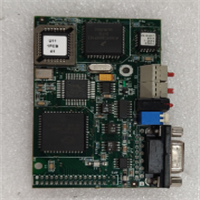
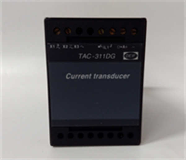
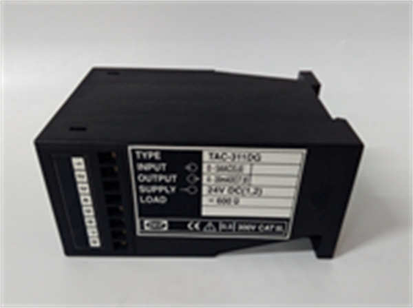
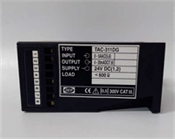
- Product Model: TAC-311DG
- Manufacturer: DEIF A/S
- System Family: TAC-300 series synchronizing controllers
- Input Signals: Generator and bus voltage (typically 100–690 V AC via PTs), frequency measurement
- Output Relays: Circuit breaker close command, raise/lower speed/fuel, raise/lower excitation
- Synchronization Method: Direct (slip-based) with adjustable closing lead time
- Display: 7-segment LED or basic LCD (depending on revision)
- Communication: None or optional RS-485 (Modbus RTU in later variants—rare for DG suffix)
- Power Supply: 24–230 V AC/DC (universal input, internal switching supply)
- Mounting: Panel-mounted, 1/4 DIN or similar format
- Environmental Rating: IP20, operating temperature 0°C to +55°C
System Role and Downtime Impact
The DEIF TAC-311DG is a standalone automatic synchronizer commonly deployed in industrial standby power systems, marine vessels, and small islanded grids. It automates the critical process of connecting a generator to an energized bus or utility grid by continuously comparing voltage magnitude, frequency difference, and phase angle between the two sources. Upon meeting preset sync windows, it issues a close command to the generator circuit breaker. In applications without manual backup or redundant sync logic, failure of the TAC-311DG prevents automatic paralleling—forcing operators into risky manual synchronization or leaving the generator offline during outages. This can result in extended facility downtime, loss of redundancy in critical infrastructure, or failure to meet emergency power requirements during grid disturbances.
Reliability Analysis and Common Failure Modes
Although designed for industrial use, the TAC-311DG—typically manufactured in the late 1990s to early 2000s—is now vulnerable to age-related degradation. The most common failure points include the internal switching power supply, where electrolytic capacitors dry out and cause intermittent resets or complete power loss. Voltage sensing circuits may drift due to aging resistors or optocoupler degradation, leading to incorrect sync decisions (e.g., closing out-of-phase). Relay contacts on the output stage can become pitted or welded from repeated switching, especially if controlling high-inductance loads without proper suppression. Additionally, exposure to humidity or conductive dust in switchgear rooms can cause PCB leakage currents or corrosion on terminal blocks.
Preventive maintenance should include periodic functional testing using a sync simulator or controlled generator run-up, visual inspection for bulging capacitors, verification of relay operation via loop-back tests, and cleaning of ventilation slots. Given its role in safety-critical operations, units showing any instability during testing should be replaced immediately.
DEIF TAC-311DG
Lifecycle Status and Migration Strategy
DEIF has officially discontinued the TAC-300 series, including the TAC-311DG, with no direct replacement offered under the same product line. The company now focuses on integrated solutions within its AGC (Automatic Generator Control) and PPC (Power Plant Controller) platforms. As a result, new TAC-311DG units are unavailable, and factory repair services have been phased out. Remaining inventory exists only through third-party brokers, often at premium pricing and without performance guarantees.
Short-term risk mitigation includes maintaining at least one verified spare unit and implementing manual sync procedures as a fallback. For long-term reliability, DEIF recommends upgrading to modern alternatives such as the AGC-4 or PPC-3 series, which provide advanced synchronization, load sharing, and black-start capabilities in a single device. These newer controllers support digital communication (Modbus TCP, CANopen), remote monitoring, and compliance with current grid codes. Migration typically requires replacing the TAC-311DG with a new controller, reconfiguring I/O wiring, and updating the human-machine interface—but retains compatibility with existing voltage transformers and breaker control circuits. This transition not only resolves obsolescence but also enhances system resilience and operational intelligence.