
 Tel:
Tel:  Email:
  WhatsApp:
 Description
Key Technical Specifications
| Parameter | Specification | Notes |
|---|---|---|
| Channels | 4 Independent | Configurable per channel |
| Input Types | Proximitor (-24V DC) or Seismometer (IEPE) | Jumper selectable or auto-sense depending on revision |
| Frequency Range | 0.5 Hz to 10 kHz (Prox); 1 Hz to 1 kHz (Seismo) | Depends on sensor and filter settings |
| Update Rate | 1 ms typical | Fast enough for high-speed trips |
| Trip Relay Output | Form C (SPDT) | De-energized to trip (safety default) |
| Power Supply | +24 VDC (Nominal) | Accepts range +18 to +32 VDC; Redundant inputs |
| Operating Temp | -20°C to +65°C (-4°F to +149°F) | Derate above 50°C for high density racks |
| Dimensions | 3HU (Half-height 3500 module) | Fits standard 3500 rack slots |
| Communication | 3500 Backplane (to 3500/25 Gateway) | No direct Ethernet; requires gateway card |
| Accuracy | ±1% of full scale | Typical at 25°C |
| Compliance | API 670, SIL 2 (with specific config) | Check certification docs for specific plant requirements |
| Bypass Feature | Software configurable | Allows maintenance without tripping machine |
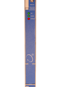
Product Introduction
When a 50,000 HP compressor starts shaking, you don’t have time to debug code or wait for a cloud server to wake up. You need hardware that reacts in milliseconds and physically cuts power before the rotor touches the stator. The Bently Nevada 3500/42-01-00 is that hardware. It’s the brain behind the brawn in thousands of oil refineries and power plants, taking raw voltage spikes from proximity probes and accelerometers and making the life-or-death decision to trip the machine.I’ve installed hundreds of these cards over two decades. The reason this specific model (-01-00) stays in spec sheets isn’t because it’s fancy; it’s because it’s stubbornly reliable. It handles both eddy current probes for shaft vibration and seismic sensors for casing shake on the same card, which simplifies rack layout. The real metric that matters here is the 1 ms update rate. I’ve seen slower monitors miss the initial spike of a rub event, allowing damage to propagate. This card catches it. One warning though: the firmware version on the label matters. Older revisions had a quirky bug where rapid power cycling could cause a false “Channel OK” LED flash while the relay remained stuck. Always verify the firmware revision against the latest Bently advisory before putting it into a critical safety loop.
 Quality SOP & Tech Pitfalls (The Reality Check)
 Quality SOP & Tech Pitfalls (The Reality Check)
The Lab Report (SOP)
We don’t just plug it in and hope. Every 3500/42-01-00 gets a full functional simulation. We use a Bently Nevada TK-3 simulator (or equivalent precision signal generator) to inject precise mils-of-displacement signals into all four channels simultaneously. We verify that Alarm 1 triggers at exactly the setpoint (e.g., 4.0 mils) and that the Trip Relay drops out within 5 ms of crossing the trip threshold (e.g., 6.0 mils). We check the “Bypass” logic to ensure it inhibits the trip but still logs the alarm. We also measure the noise floor on the inputs; if we see more than 20 mV of random noise with no input, the card’s analog front end is suspect, and we reject it. Finally, we inspect the backplane connectors for bent pins—a common shipping hazard—and seal it in anti-static packaging with a printed test log.The Engineer’s Warning (Pitfalls)
The number one killer of these cards isn’t failure; it’s configuration mismatch. The 3500 system relies on the 3500/25 Gateway to download configuration data to the monitor cards at power-up. If your gateway has an old config file, or if you swap a card and forget to force a config download, the new card might sit there with factory default setpoints (often zero or maxed out), leaving your machine unprotected. I witnessed a fan train destroy itself because the new replacement card had a trip setting of 20 mils instead of the required 6 mils, simply because the engineer assumed the rack would “remember.” It won’t. Also, watch your grounding. The 3500 rack must be bonded to the plant ground with a low-impedance strap. I’ve seen noisy grounds induce 60Hz hum that looked like sub-synchronous whirl, causing nuisance trips that took days to diagnose. Check your ground strap first.
Installation & Configuration Guide
Phase 1: Pre-Installation
⚠️ STOP. Ensure the 3500 rack power is OFF. If the rack is live, you risk shorting the backplane. Before removing the old card, access the System 1 software or the local HMI and save the current configuration file. Take a photo of the DIP switches (if any) and the wiring termination at the rear of the rack. Verify the slot number; 3500 monitors are often slot-specific in the configuration logic.Phase 2: Removal
Unscrew the front panel mounting screws. Some racks have locking levers; disengage them carefully. Pull the card straight out. Do not wiggle it excessively, as this can damage the 96-pin backplane connector. Inspect the backplane socket for debris or bent pins immediately. If pins are bent, stop and repair the rack before proceeding.Phase 3: Installation
Align the new 3500/42-01-00 with the slot guides. Push firmly and evenly until the card seats completely against the backplane. You should feel a solid stop. Secure the front panel screws and engage any locking levers. Re-connect the field wiring to the terminal blocks (usually I/O modules mounted next to the card). Double-check polarity on the DC supply inputs. Critical Step: Do not assume the card is ready. You must initiate a “Download Configuration” command from the 3500 Gateway interface to push the correct setpoints, delays, and bypass states to the new card.Phase 4: Power-On & Testing
Restore power to the rack. Watch the LED sequence. The “OK” LED should turn solid green after the self-test (approx. 5-10 seconds). If it flashes red/green, check the gateway for error messages. Use a signal simulator to inject a test signal into Channel 1. Verify that the displayed value on the HMI matches the injected signal and that the Alarm/Trip relays activate at the correct thresholds. Repeat for all four channels. Document the “As-Found” and “As-Left” data.
Compatible Replacement Models
 Compatible Replacement Models
| Compatibility Tier | Model Number | Details & Differences |
|---|---|---|
| ✅ Drop-in Replacement | 3500/42-01-00 | Exact match. Same hardware, same firmware baseline. No logic changes required. |
| ✅ Drop-in Replacement | 3500/42M-01-00 | The “M” denotes a slightly updated manufacturing revision with improved ESD protection. Functionally identical. Pin-for-pin compatible. |
| ⚠️ Software Compatible | 3500/42-02-00 | Similar hardware but may support different sensor types (e.g., specialized velocity inputs). Requires verifying the configuration file supports the specific input type selected. |
| ❌ Hardware Mod Required | 3500/25 (Gateway Card) | Not a replacement. This is the communication card. Confusing the two will result in a non-functional rack. |
| ❌ Obsolete | 3300/16 (Legacy) | Older 3300 series system. Different form factor, different backplane, different logic. Requires full rack retrofit. |
Frequently Asked Questions (FAQ)
Q: Can I swap this card while the machine is running?
A: Technically, the 3500 system supports “online replacement” for some cards if configured for redundancy, but for a single monitor card like the 3500/42? No. Removing it breaks the circuit continuity for the trip relays. Unless you have external voting logic or a fully redundant parallel system, pulling this card will likely trip the machine immediately. Plan a shutdown or use a maintenance bypass switch if your safety instrumented system (SIS) allows it.Q: My new card shows a flashing red LED. Is it broken?
A: Not necessarily. A flashing red LED usually means “Configuration Mismatch” or “Missing Config.” The card is powered and healthy, but it hasn’t received its operating parameters from the 3500/25 Gateway yet. Connect to the rack via the System 1 software or the local display and force a configuration download. If it stays red after that, then you might have a hardware fault or a backplane connection issue.Q: Does this card work with my old -24V DC Bently probes?
A: Yes. The “-01-00” suffix specifically indicates support for standard Bently Nevada proximitor sensors requiring -24 VDC bias. It also supports IEPE seismic sensors. Just ensure you configure the channel type correctly in the software (Proximitor vs. Seismometer) so the internal filtering and scaling match your sensor.Q: How do I handle the “Bypass” function during maintenance?
A: Never jump wires to bypass a trip. Use the software. The 3500 system allows you to logically “Bypass” a channel via the Gateway interface. This inhibits the trip relay from activating due to that specific channel while still recording alarms. This is safer and auditable. Remember to remove the bypass immediately after work is complete; leaving a protection loop bypassed is a major safety violation.Q: What is the lead time if this is out of stock?
A: Genuine Bently Nevada cards can sometimes have lead times of 12-20 weeks if not in distributor stock. Be wary of “immediate shipment” offers from unknown sellers; the market is flooded with refurbished cards with cracked solder joints or fake labels. We test every unit. If we say it’s in stock, it’s on the shelf ready to ship today. Don’t gamble your turbine on a $50 eBay special.