 Tel:
Tel:  Email:
  WhatsApp:
 Description
Key Technical Specifications
| Parameter | Specification |
|---|---|
| Model Number | 3500/33 149992-01 |
| Input Type | Proximity Probe (Eddy Current) |
| Output Signal | 4-20mA or ±10VDC (Selectable) |
| Power Supply | 120VAC / 24VDC (Dual Redundant) |
| Channels | 2 Channels (Per Module) |
| Mounting | DIN Rail (35mm) |
| Operating Temp | -20°C to 60°C (68°F to 140°F) |
| Certifications | cULus Listed (Class 1, Div 2) |
| Communication | 3500 System Bus (Serial) |
| Dimensions | 100 x 150 x 50 mm (Approx) |
Product Introduction
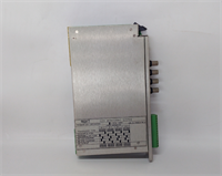
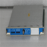
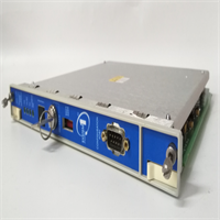
The BENTLY 3500/33 149992-01 is the workhorse of the 3500 system, acting as the bridge between your precious rotating assets and the control room. I’ve seen these modules deployed on steam turbines and compressors where downtime is measured in thousands of dollars per minute. This specific revision (149992-01) is the standard issue for most modern 3500 configurations, providing a solid interface for your proximity probes.From a reliability standpoint, this module is built like a tank. It handles the harsh realities of the plant floor—electrical noise and temperature swings—with ease. It supports dual redundant power supplies, which is a lifesaver when you’re trying to isolate a fault without tripping the entire unit. While it’s a mature design, it remains the industry standard for converting mechanical motion into a digital signal that the 3500 rack can understand and act upon.
Bently 3500/33 149992-01 Vibration Input Module
Quality SOP & Tech Pitfalls
The Quality Assurance Protocol
Before this module leaves my bench, I run it through a battery of tests that mimic a real plant environment. First, I perform a visual forensic analysis to check for corrosion or physical damage. Then, it hits the Live Test Rack where I simulate input signals to verify the output matches the expected values. I use a Fluke 115 to check the insulation resistance and ensure the DC power supply is clean. Finally, I log the firmware version and verify it matches the original. Only after passing the “bench burn-in” does it get packaged in anti-static bags with desiccant.The Field Engineer’s Warning
Installing this module is straightforward, but there are two critical “gotchas” that can turn a simple swap into a day-long nightmare.
- The DIP Switch Debacle: Never, ever swap this module without taking a photo of the old DIP switch settings. The address codes on this module determine how the 3500 system identifies it. Changing them by accident will result in a “Module Not Found” error that is incredibly difficult to troubleshoot without the serial number in hand.
- ESD Damage: This module is extremely sensitive to electrostatic discharge. Even though it’s a rugged industrial component, a static shock during handling can damage the internal ASICs. I always ground myself to the chassis before touching it, and I recommend using an ESD wrist strap if you have one.
Installation & Configuration Guide
Phase 1: The Shutdown (Safety First ⚠️)
- Power Down: Kill the power to the entire 3500 chassis. Wait the mandatory 10 minutes to allow the capacitors to discharge. I’ve seen guys get zapped because they didn’t wait.
- Label Everything: Before you touch a screw, take high-resolution photos of the wiring. Label each wire with its terminal number using masking tape. This is the most important step; don’t skip it.
Phase 2: Removal
- Release the DIN Clip: Locate the locking tab on the DIN rail. Press it down and slide the module out. Do not pull straight up or you might bend the pins on the backplane.
- Unplug the Cables: Carefully disconnect the sensor leads and the power cables. Keep them organized.
Phase 3: Installation
- Copy the Settings: Using your photos, replicate the DIP switch positions exactly on the new module. This is the difference between a working system and a scrambled error code.
- Seat the Module: Align the module with the backplane connector and push it firmly into the DIN rail until it clicks.
Phase 4: Power-On & Testing
- Restore Power: Flip the breaker. Watch the LEDs; they should go through a normal boot sequence (Power Good, System OK).
- Verify Output: Once powered, check the output signal with a multimeter. It should read within the expected range of your sensor’s calibration.
- Download Logic: If you’re changing firmware or configuration, download the logic and verify the module ID in the 3500 software matches the new hardware.
Compatible Replacement Models
| Model Number | Compatibility | Notes |
|---|---|---|
| 3500/33 149992-01 | ✅ Drop-in | Exact match, no changes required. |
| 3500/33 149992-02 | ⚠️ Software | Same hardware, but different firmware version. May require a logic recompile if the version difference is significant. |
| 3500/33 149992-03 | ⚠️ Software | Supports newer protocols but is mechanically identical. |
| 3500/33 149992-04 | ⚠️ Software | Field-replaceable firmware, but requires specific programming tools. |
Frequently Asked Questions (FAQ)
Q: Can I hot-swap this module while the system is running?
A: Technically, the 3500 system supports hot-swapping, but I strongly advise against it. If the module has failed, you should power down the chassis to prevent potential damage to the backplane or other modules. If it’s a planned maintenance swap, ensure the system is in “Maintenance” mode to avoid false alarms.Q: What’s the difference between revision 01 and 02?
A: The primary difference is firmware and minor electrical tolerances. Revision 02 often includes bug fixes for specific sensor compatibility issues. If you’re replacing a 02 with a 01, it usually works, but you might need to adjust the calibration offset slightly in the software.Q: Is this module compatible with the older 3300 system?
A: No. The 3500/33 is designed specifically for the 3500 chassis and uses a different communication protocol. You cannot plug a 3500 module into a 3300 backplane, nor can you use a 3300 module in a 3500 rack.Q: How do I know if the module is bad or if the issue is the sensor?
A: This is a classic case of “garbage in, garbage out.” If the module’s front-panel LEDs are flashing erratically or showing a “No Signal” fault, it’s likely the sensor or cabling. If the LEDs show “OK” but the output signal is drifting or reading zero, the module is likely at fault. Use a multimeter to check the DC power supply first; a bad supply will kill the module instantly.Q: What’s the shelf life of a new-old-stock (NOS) module like this?
A: As long as the firmware version matches and the battery (if applicable) is intact, these modules are built to last. I’ve seen NOS units from the 90s that are still running strong. The electrolytic capacitors are usually the first to fail, so if the unit has been sitting for over 10 years, I recommend a visual inspection for bulging cans.