 Tel:
Tel:  Email:
  WhatsApp:
 Description
Key Technical Specifications (For Spare Parts Verification)
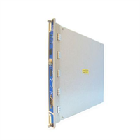
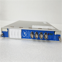
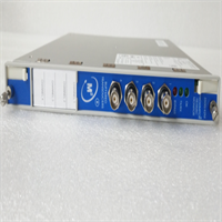
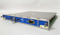
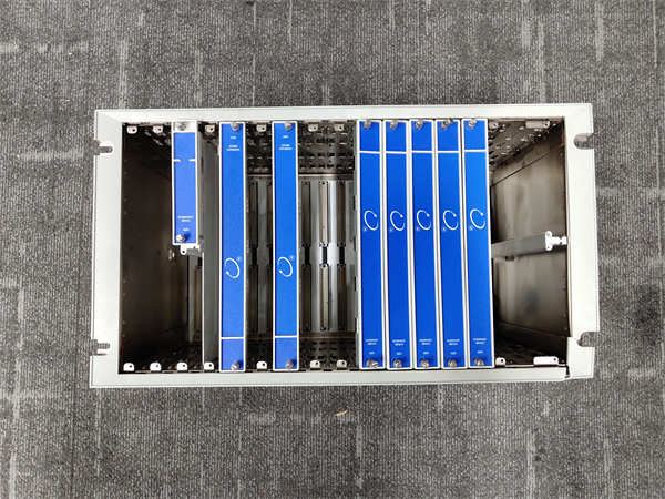
- Product Model: 3500/05-01-02-00-00-00
- Manufacturer: Bently Nevada
- System Platform: 3500 Machinery Protection System
- Module Type: Chassis Interface Module (CIM)
- Slot Position: Installed in Slot 3 of the 3500 rack (immediately right of power supplies)
- Primary Function: Enables backplane communication between I/O modules and relay cards (e.g., 3500/53); stores chassis configuration via DIP switches or internal memory
- Configuration Method: Hardware DIP switches (for older revisions) or software-defined (via 3500/25 Configurator)
- Status Indicators: “OK” and “Fault” LEDs on front panel
- Connector Type: Integrates directly with 3500 backplane; no external field wiring
- Firmware Dependency: Must be compatible with installed I/O and relay modules (version mismatch can cause boot failure)
System Role and Downtime Impact
The 3500/05-01-02-00-00-00 is the central nervous system of the 3500 chassis. It enables module-to-module communication across the backplane and ensures the protection relay (such as the 3500/53) receives valid, synchronized data from all input cards (vibration, position, speed). If this module fails or becomes misconfigured, the entire rack may fail to boot, or the relay may receive corrupted or missing data. In either case, the machinery protection logic cannot execute reliably—often resulting in a “system fault” trip that forces an immediate shutdown of the associated turbine, compressor, or pump. Unlike I/O modules, the CIM has no redundancy; its failure directly compromises the integrity of the entire safety layer.
Reliability Analysis and Common Failure Modes
Although solid-state in design, the 3500/05 module is susceptible to age-related degradation due to prolonged thermal cycling and exposure to electrical noise in industrial environments. Common failure modes include: corruption of internal configuration memory (especially in early EEPROM-based versions), solder joint fatigue on the backplane connector, and logic IC failure due to voltage transients on the backplane. A key vulnerability is its dependency on precise firmware compatibility—mixing modules from different production batches can lead to initialization errors that mimic hardware failure. Additionally, dust accumulation and poor ventilation in control cabinets accelerate component aging.
Preventive maintenance should focus on: verifying LED status during routine rounds; ensuring cabinet temperature remains within specification; inspecting for signs of overheating or discoloration on the module surface; and maintaining accurate records of firmware and hardware revisions across all 3500 components. Avoid hot-swapping unless explicitly supported by the revision—mechanical stress can damage fragile backplane pins.

BENTLY 3500/05-01-02-00-00-00
Lifecycle Status and Migration Strategy
Bently Nevada has discontinued the 3500/05 series, and official support is no longer available. Continuing to operate with this module carries significant risk: no factory replacements, limited repair options, and increasing difficulty in diagnosing configuration-related faults. As temporary measures, facilities should secure at least one verified-good spare unit and document its exact revision and switch settings. Third-party board-level repair is possible but requires deep expertise in legacy Bently hardware.
The long-term solution is migration to a modern platform. Bently Nevada’s recommended path is transition to the System 1 Condition Monitoring Platform, which replaces discrete 3500 racks with scalable, software-defined architecture. Alternatively, for protection-only applications, integration with a certified SIL-compliant PLC (e.g., using API 670-compliant analog inputs) may be viable. Both paths require revalidation of all alarm and trip logic, sensor compatibility checks, and updated integration with plant safety systems. A detailed gap analysis is essential before initiating any migration project.