
 Tel:
Tel:  Email:
  WhatsApp:
 Description
Key Technical Specifications (For Spare Parts Verification)
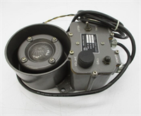
- Product Model: SIR4-S11
- Manufacturer: ALSTOM T&D (legacy product line)
- System Family: SIR4 numerical protection relay series
- Protection Functions: 3-phase overcurrent (50/51), earth fault (50N/51N), distance protection (21), breaker failure (50BF)
- Input Channels: 3 voltage (VT) and 3 current (CT) analog inputs (standard); optional auxiliary CTs
- Output Contacts: Minimum 6 programmable output relays (typically 8–10 available)
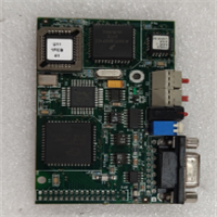
- Communication Interface: RS-485 with Modbus RTU (optional); no Ethernet or IEC 61850 support
- Auxiliary Supply: 24–250 V DC or 110/230 V AC (field-configurable via internal jumpers)
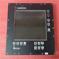
- Setting Method: Front keypad with LCD display; settings stored in non-volatile memory
- Standards Compliance: IEC 60255, IEEE C37.90
- Mounting: 19-inch rack or panel mount with removable terminal blocks
System Role and Downtime Impact
The SIR4-S11 was widely deployed in transmission and distribution substations from the late 1990s through early 2000s as a digital upgrade path from electromechanical relays. It provides coordinated fault detection and isolation for critical overhead lines and cable feeders. In its role, it interfaces directly with circuit breakers and upstream/downstream protection devices to maintain selective tripping during faults.
If this relay fails or malfunctions:
- Loss of primary or backup protection for a transmission feeder
- Potential for uncoordinated tripping, leading to wider area outages
- Regulatory non-compliance with modern grid code requirements (e.g., lack of event recording or time synchronization)
- Extended outage duration due to difficulty sourcing and configuring replacement units
Given its role in grid reliability, unplanned failure can trigger mandatory incident reviews by transmission system operators (TSOs) and incur significant operational penalties.
Reliability Analysis and Common Failure Modes
Although built to utility-grade standards, the SIR4-S11 is now operating far beyond its design life. Common failure modes include:
- Internal battery depletion: Units use a lithium backup battery to retain settings and event logs; after 10–15 years, battery failure causes complete loss of configuration on power loss
- Keypad and display degradation: Membrane keypad contacts oxidize, and LCD contrast fades, making local operation unreliable
- Power supply capacitor aging: Electrolytic capacitors in the auxiliary supply section dry out, causing undervoltage resets during system transients
- Communication port failure: RS-485 transceivers degrade due to ground potential rise or lightning-induced surges, breaking SCADA telemetry
Recommended preventive actions:
- Export and archive all relay settings and event records annually via front panel or serial port
- Replace internal backup battery every 8–10 years (requires unit de-energization and recalibration)
- Verify trip coil supervision and output contact continuity during routine maintenance
- Maintain at least one pre-configured spare per substation, tested under simulated fault conditions
Lifecycle Status and Migration Strategy
ALSTOM’s T&D division was divested in 2006, and the SIR4 product line was discontinued shortly thereafter. GE Grid Solutions (current rights holder) no longer provides repair services, firmware updates, or technical documentation for the SIR4 series.
Continued use presents escalating risks:
- No cybersecurity features (a growing concern for grid assets)
- Incompatibility with modern SCADA protocols (e.g., IEC 61850, DNP3 Secure Authentication)
- Lack of event waveform capture meeting current NERC/FERC requirements
Interim solutions include:
- Sourcing tested units from certified relay refurbishers with full functional validation
- Installing external protocol converters to bridge Modbus RTU to modern SCADA systems
- Implementing redundant external overcurrent elements as backup
The recommended migration path is replacement with GE’s MiCOM P446 or P448 relays, which offer direct functional equivalence with added benefits: IEC 61850 GOOSE, synchrophasor measurement, cyber-hardened architecture, and seamless integration into GE’s Enervista UR software suite. Migration requires CT/VT ratio verification, protection coordination study update, and re-engineering of control wiring—but restores compliance, supportability, and long-term operational resilience.