 Tel:
Tel:  Email:
  WhatsApp:
 Description
Key Technical Specifications
- Application: Transmission Lines (HV/EHV), Generator Step-Up Transformers
- Protection Functions:
- Distance (21): 4 forward zones, 1 reverse zone (Quadrilateral or Mho characteristics)
- Overcurrent (50/51): 3-phase and Earth Fault
- Auto-reclose (79): Multi-shot capability with sync check
- Power Swing Blocking (68)
- Weak Infeed Logic
- Input Voltage (Auxiliary): 24-250V DC or 110-240V AC (Check specific order code suffix)
- CT Input: 1A or 5A secondary (Software selectable)
- VT Input: 100V, 110V, 115V, 120V (Software selectable)
- Communication Ports: Front USB, Rear Ethernet (IEC 61850), RS485 (Modbus/DNP3)
- Operating Temperature: -25°C to +70°C
- Storage Temperature: -40°C to +85°C
- Humidity: 5% to 95% non-condensing
- Trip Time: < 20ms for Zone 1 faults (typical)
- Memory: Event log > 1000 records; Disturbance recorder (oscillography) up to 10 seconds.
Product Introduction
In the world of transmission protection, you don’t get second chances. If a fault hits a 230kV line, the relay needs to see it, decide, and trip the breaker before the system destabilizes. The Alstom IR139-1 (MiCOM P40 Agile) is the workhorse I’ve relied on for clearing faults in complex grid topologies. It replaced the older P44x series with a more agile processor and better cybersecurity features, but kept the robust DNA that Alstom relays are known for.I’ve deployed these in substations where communication latency is a nightmare, and the IEC 61850 GOOSE messaging on this unit handles peer-to-peer tripping faster than hardwired pilot wires ever could. The “Agile” platform means the HMI is actually usable—you can navigate settings without needing a PhD in menu structures. However, don’t let the modern interface fool you; the internal logic is heavy-duty. It handles power swings and CT saturation better than most competitors in its class. Just make sure your CT burden calculations are tight; this relay is sensitive, and sloppy wiring will give you nuisance trips during external faults.
Quality SOP & Tech Pitfalls (The Reality Check)
The Lab Report (SOP)
Testing a distance relay like the IR139-1 requires more than just injecting current. We start with a visual inspection of the terminal screws and the LCD display for dead pixels. Then, we use an Omicron CMC 356 test set to simulate faults at various impedance angles. We verify the reach of Zone 1 (typically 80% of line length) and ensure Zone 2/3 time delays are precise. We specifically test the Power Swing Blocking (PSB) function by ramping impedance slowly to ensure it doesn’t trip on stable swings. Finally, we verify the IEC 61850 configuration by sending GOOSE messages from a simulator and confirming the relay reacts within 4ms. We seal it with the tested firmware hash recorded.
The Engineer’s Warning (Pitfalls)
The biggest trap with the MiCOM P40 series is the VT (Voltage Transformer) supervision. If you wire the VTs incorrectly or leave a fuse blown, the relay might see a “low voltage” condition and misinterpret it as a close-in fault, tripping Zone 1 instantly. I once saw a commissioning team skip the VT polarity check, resulting in a directional earth fault element seeing reverse faults as forward. Another critical issue: Time Synchronization. If you are using IEC 61850 for event timestamping, ensure the SNTP or IRIG-B clock is synced. Without it, troubleshooting a grid disturbance becomes a guessing game because your event logs won’t align with the SCADA historian. Also, watch out for the “Test Mode” switch; leaving it enabled blocks trip outputs, which is great for testing but disastrous if forgotten during energization.
Installation & Configuration Guide
Time Estimate: 60 Minutes (Includes Basic Config)
- Pre-Installation Safety ⚠️
- LOTO: Isolate all DC control power and VT/CT secondary circuits. Short the CT secondaries before disconnecting to prevent high voltage spikes.
- Critical: Download the existing settings file from the old relay (if functional) or retrieve the approved setting sheet from the protection engineer. Do not rely on memory.
- Removal
- Label every wire at the terminal block. Use a permanent marker. Transmission wiring is dense; one swapped wire can reverse directional elements.
- Remove the terminal block plugs first, then unscrew the mounting brackets.
- Slide the relay out. Support the weight; these units are metal-cased and heavy.
- Installation
- DIP Switches/Jumpers: Check the rear DIP switches for CT ratio (1A/5A) and Aux Voltage selection. Match these to your site hardware before applying power.
- Mount the IR139-1 into the 19-inch rack or flush panel cutout. Secure firmly.
- Re-terminate wires. Torque terminals to manufacturer spec (usually 2.0 – 2.5 Nm for power, 0.6 Nm for signals).
- Connect Comms: Plug in the Ethernet cable for the station bus. Ensure the VLAN tag (if used) matches the switch config.
- Power-On & Testing
- Apply Aux Power. The LED should turn green, and the LCD should boot up.
- Check Health: Navigate to the “Self-Test” menu. Ensure no hardware errors (EEPROM, RAM, ADC) are present.
- Verify Settings: Connect a laptop via USB or Ethernet (using Alstom/GE MiCOM S1 Studio or Enervista). Upload the approved settings file. Verify the checksum.
- Secondary Injection: Inject a low-level current (e.g., 0.5A) to verify the relay sees the correct magnitude and angle. Check the “Measured Values” screen.
- Trip Circuit Test: Manually trigger a test trip (via software) and verify the output relay clicks and the breaker trip coil circuit is intact (using a lamp or multimeter, not actually tripping the live breaker).
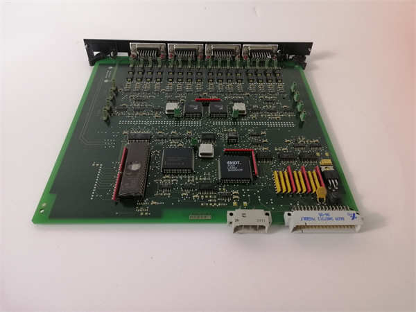
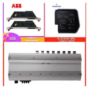
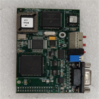
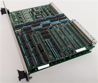
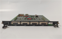
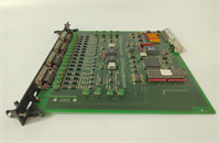
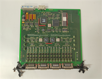
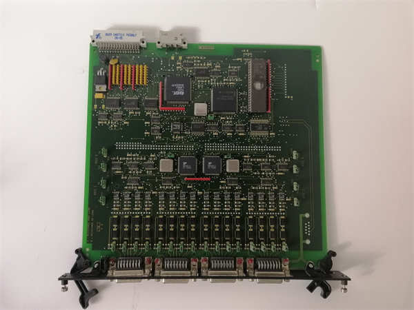
IR139-1 ALSTOM
Compatible Replacement Models
- ✅ Drop-in Replacement: IR139-2 or IR139-3.
- Note: These are newer hardware revisions of the same Agile platform. Pinout and dimensions are identical. Firmware may be newer, offering enhanced cyber security or IEC 61850 Edition 2 support.
- ⚠️ Software Compatible: P442 or P444 (Legacy MiCOM).
- Warning: Older generation. Physically similar but mounting clips and terminal depth might differ slightly. Settings files are not directly compatible; they must be converted using GE migration tools. Only use if upgrading an old bay and you have engineering support for conversion.
- ❌ Hardware Mod Required: P34x (Generator Protection) or P24x (Distribution).
- Advice: Different form factors and protection algorithms. A generator differential relay cannot replace a transmission distance relay. The logic and zone characteristics are fundamentally different.
Frequently Asked Questions (FAQ)
Is the IR139-1 compatible with IEC 61850 Edition 2?
Most IR139-1 units shipped after 2018 support Ed2, but it depends on the specific firmware version loaded. Check the label or connect via S1 Studio to verify. If your substation requires Ed2 for GOOSE subscription, you may need to upgrade the firmware (which requires a license key from GE Grid Solutions).Can I use this relay for distribution lines (e.g., 33kV)?
Technically yes, it will work, but it’s overkill and expensive. The IR139-1 is optimized for transmission complexities (power swings, mutual coupling, long lines). For 33kV distribution, the Alstom P24x or P14x series is more cost-effective and easier to configure for simple overcurrent/earth fault schemes.My relay shows a “VT Fuse Fail” alarm, but the fuses are fine. Why?
This is often a setting issue. The relay calculates negative sequence voltage to detect fuse failures. If your system is unbalanced (common in weak grids) or during single-pole reclosing, the relay might falsely interpret this as a blown fuse. Check the “VT Supervision” settings and adjust the threshold or time delay to ride through temporary unbalances.How do I extract the disturbance record (oscillography) after a trip?
Connect via the front USB port or rear Ethernet using MiCOM S1 Studio or Enervista. Navigate to the “Disturbance Recorder” section. You can export the COMTRADE file (.cfg and .dat) directly. This file can be opened in analysis software like Sigra or the GE viewer to see the exact waveform of the fault.What is the difference between Alstom and GE branding on these relays?
GE acquired Alstom’s Grid business in 2015. Newer units might say “GE Grid Solutions” while older stock says “Alstom.” The hardware (IR139-1) and software (MiCOM Agile) are identical. Support and firmware updates now come through GE. If you see an “Alstom” label, it’s likely older stock, but fully supported. Just ensure the firmware is updated to patch any known cybersecurity vulnerabilities.