 Tel:
Tel:  Email:
  WhatsApp:
 Description
Key Technical Specifications (For Spare Parts Verification)
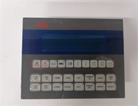
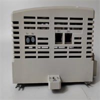
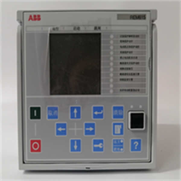
- Product Model: REM615C_D HCMJAEADAND2BNN1CD
- Manufacturer: ABB
- Product Family: SIPROTEC 4
- Base Hardware: REM615C (7UM61 platform)
- Configuration Code: HCMJAEADAND2BNN1CD (defines specific protection functions, I/O assignments, communication settings, and firmware version)
- Protection Functions: Typically includes L1/L2/L3 overcurrent, earth fault (directional or non-directional), thermal overload (for motors), auto-reclose, and breaker failure backup
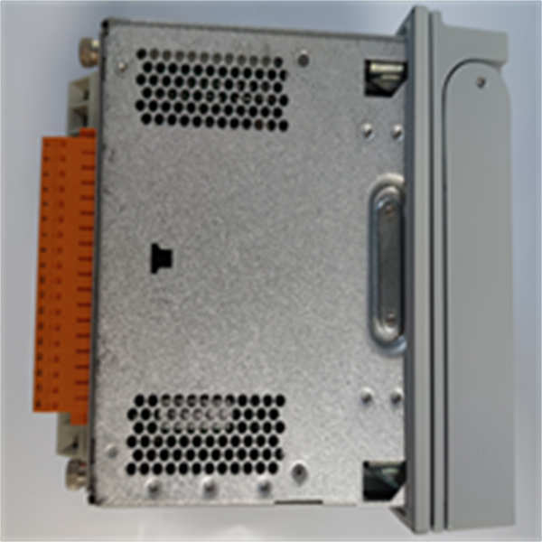
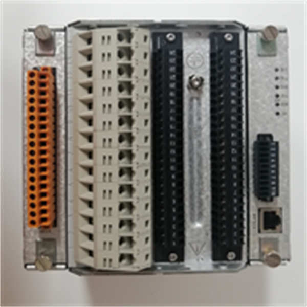
- I/O Configuration: Fixed binary inputs (e.g., 10–18), output relays (e.g., 6–10), and analog outputs based on the configuration code
- Communication Interfaces: RS485 (IEC 60870-5-103), optional Modbus RTU or Profibus DP via hardware key
- Power Supply: 24–250 VDC or 110/230 VAC (field-selectable via internal jumpers)
- Standards Compliance: IEC 60255, IEC 61000-4 (EMC immunity), IEEE C37.90
- Mounting: 19″ rack or panel mount (7U height)
System Role and Downtime Impact
The ABB REM615C_D with configuration HCMJAEADAND2BNN1CD is typically deployed in medium-voltage motor control centers (MCCs), main-tie-main switchgear, or dedicated feeder panels in oil & gas, mining, and heavy industrial facilities commissioned between the early 2000s and 2015. It integrates protection, metering, and local control logic into a single device, often interfacing directly with SCADA via serial protocols.
If this relay fails, the protected asset—whether a large induction motor, transformer feeder, or bus tie—loses all automated protection and remote operability. Operators may be forced into manual switching, increasing safety risk. In worst cases, a downstream fault could go undetected until cleared by upstream devices, causing cascading outages or severe equipment damage. Because the configuration is embedded in firmware, even a physically identical spare unit will not function correctly without proper reprogramming—a process that is now extremely difficult due to software obsolescence.
Reliability Analysis and Common Failure Modes
Despite robust construction, the REM615C is now operating well beyond its intended service life in many installations.
Common failure modes include:
- Internal power supply capacitor degradation, leading to voltage instability, spontaneous resets, or complete shutdown under load.
- RS485 communication IC failure due to ground loops or surge events, resulting in loss of SCADA visibility while local protection may still function.
- Output relay contact wear or welding, especially on frequently operated trip or close coils, causing failure to operate during faults.
- Configuration memory corruption, where the unit boots but operates with default (unsafe) settings due to EEPROM bit rot.
- Backplane connector corrosion, causing intermittent I/O dropout or module recognition errors in rack-mounted setups.
Design weaknesses include reliance on battery-backed RAM in earlier revisions (not applicable to all REM615C variants), limited event storage (<200 records), and no built-in self-test for output circuits. The custom configuration also means that field technicians cannot easily swap units without access to original engineering files.
Preventive maintenance recommendations:
- Perform annual secondary injection tests to verify all protection elements and output operations.
- Inspect and clean terminal blocks and backplane connectors during planned outages.
- Monitor DC supply quality at the relay terminals—ripple above 5% accelerates component aging.
- Secure and archive the original DIGSI 4 project file and configuration backup if still available.
- Verify event logs quarterly for signs of abnormal resets or communication errors.
REM615C_D HCMJAEADAND2BNN1CD ABB
Lifecycle Status and Migration Strategy
ABB has officially discontinued the entire SIPROTEC 4 platform, including the REM615C. The specific configuration HCMJAEADAND2BNN1CD is no longer reproducible through standard channels. DIGSI 4 software is unsupported on modern Windows versions, and license dongles are often lost or incompatible. Continuing to operate with this relay introduces significant operational and safety risk.
Interim mitigation strategies include:
- Securing a verified, functionally tested spare unit with the exact same configuration code.
- Engaging specialized third-party service providers who maintain legacy DIGSI 4 environments for emergency reconfiguration.
- Implementing external monitoring (e.g., power quality meters) to provide partial visibility if communication fails.
For permanent resolution, migration to the SIPROTEC 5 REL650 series is the recommended path. The REL650 offers native IEC 61850, enhanced cybersecurity, waveform capture, and web-based diagnostics. However, replacement is not plug-and-play:
- Requires rewiring of CTs, VTs, and I/O circuits to match new terminal layout.
- Demands full re-engineering of protection logic and coordination studies.
- Necessitates integration into a modern engineering workflow using DIGSI 5 or PCM600.
- May require updates to SCADA front-end drivers for IEC 61850 or Modbus TCP.
Executing this upgrade during a planned plant turnaround eliminates a known obsolescence vulnerability and aligns the facility with current grid code and cybersecurity standards. Until then, rigorous spares management and preventive testing are essential to maintain system integrity.