 Tel:
Tel:  Email:
  WhatsApp:
 Description
Key Technical Specifications
| Parameter | Value |
|---|---|
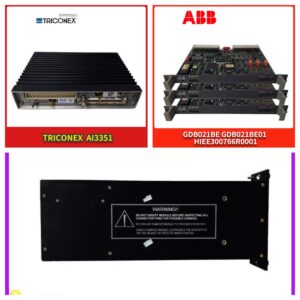
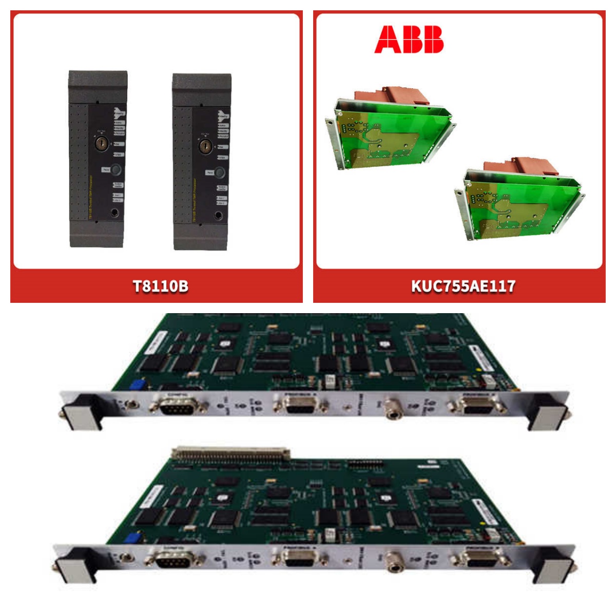
| Part Number | HIEE300900R0001 |
| Model Code | PPC322BE |
| Processor Type | 16-bit CMOS |
| Clock Frequency | 8 MHz |
| Memory | 256 KB RAM, 256 KB EPROM |
| Supply Voltage | 24 VDC (19.2–30 VDC) |
| Current Consumption | approx. 1.2 A (Logic) |
| Communication | RS-232 / RS-485 (SACE Bus) |
| Watchdog | Hardware monitored |
| Dimensions | 222 mm x 136 mm x 45 mm |
Product Introduction
The PPC322BE (HIEE300900R0001) is a processor module designed for ABB’s Advant OCS and MasterPiece systems. It handles central processing tasks, executing logic code and managing communication between I/O modules and supervisory interfaces.This unit operates at an 8 MHz clock speed, which provides sufficient processing power for standard protection and control applications. It features 256 KB of RAM for variable storage. The module supports battery-backed memory to retain critical data during power loss.
Installation & Configuration Guide
Phase 1: Preparation (10 min)
- Safety First: De-energize the rack. Lock out/Tag out (LOTO) the 24 VDC supply.
- ESD Protection: Wear a grounded wrist strap. The CMOS chips on the PPC322BE are sensitive to static discharge.
- Tools: Phillips screwdriver (size 2), anti-static mat.
- Inspection: Check the PCB for corrosion or burnt components, specifically near the voltage regulators.
Phase 2: Removal (5–10 min)
- Disconnect: Unplug the RS-232/485 communication cables.
- Eject: Loosen the captive screws on the front panel. Use the ejector levers (if equipped) to disengage the card from the backplane.
- Extract: Pull the module straight out. Do not rock it side-to-side to avoid bending backplane pins.
Phase 3: Installation (10 min)
- Configuration: Check DIP switches. Ensure the “Termination” switch is set correctly if this is the last node on the bus.
- Insert: Align the guides with the rack slot. Slide the module in firmly until the backplane connector seats.
- Secure: Tighten the front panel screws to ensure proper grounding (EMC compliance).
Phase 4: Power-On & Test (10 min)
- Apply Power: Restore 24 VDC to the rack.
- Observe LEDs:
- RUN: Should flash or stay solid (indicates program execution).
- FAULT: Must be OFF.
- COM: Should toggle during data exchange.
- Verify: Connect a PC via the service port to check the “Online” status in the configuration software.
Troubleshooting Quick Reference
| Symptom | Probable Cause | Corrective Action |
|---|---|---|
| RUN LED OFF | No power or Watchdog trip | Check 24 VDC input at terminals. Replace backup battery. |
| FAULT LED ON | Memory error or Firmware corrupt | Cycle power. If persistent, reload firmware or replace unit. |
| No Communication | Baud rate mismatch | Verify DIP switch settings match the master station. |
| System Resets | Brownout or Noise | Check power supply ripple. Verify grounding connections. |
| Battery Low Alarm | Dead backup battery | Replace the onboard lithium battery (typically CR2032 or similar). |
Dimensions, Mounting & Wiring Notes
- Dimensions: 222 mm (H) x 136 mm (W) x 45 mm (D).
- Mounting: Designed for vertical mounting in standard 19-inch racks or ABB-specific subracks.
- Wiring:
- Power: 24 VDC input is typically routed through the backplane, but verify auxiliary power terminals if present.
- Comms: Use shielded twisted pair for RS-485 connections. Keep communication cables away from high-voltage lines (>100 mm separation).
- Torque: Tighten terminal screws to 0.5–0.6 Nm.

FAQ
Q: Can I replace my old PPC321 with this PPC322BE?
A: Generally, yes. The PPC322BE is the enhanced version. However, you must verify that your firmware version is compatible. The physical dimensions and pinouts are usually identical, but check the “BE” suffix requirements in your system manual.Q: What does the “BE” in PPC322BE stand for?
A: It typically denotes a specific hardware revision or “Basic” configuration with Ethernet/Enhanced communication capabilities depending on the sub-variant. Always check the label on the front plate.Q: The FAULT light is flashing red. Is it broken?
A: Not necessarily. A flashing fault light often indicates a specific error code. Connect via the service port to read the event log. It could be a simple battery low warning or a memory checksum error.Q: Do you supply the rack backplane?
A: No, we supply the module only. You will need to install this into your existing MasterPiece or Advant OCS rack.Q: How do I know if the battery is good?
A: Measure the voltage across the battery holder contacts on the PCB. It should be >3.0 VDC. If it drops below 2.7 VDC, replace it immediately to prevent program loss.Q: Is this item tested before shipping?
A: Yes. We perform a power-up test to verify the LED status and check for short circuits on the main supply rails. We do not run a full logic simulation.