 Tel:
Tel:  Email:
  WhatsApp:
 Description
Key Technical Specifications
- Number of Channels: 8 independent relay outputs
- Contact Type: Form C (SPDT – Single Pole Double Throw), NO/NC/COM available
- Switching Voltage: 24V DC to 230V AC (Max 250V)
- Continuous Current: 2A per channel (Resistive load)
- Maximum Switching Current: 2A (AC-15 inductive load derating applies, typically 0.5A for solenoids)
- Insulation Voltage: 250V AC between channels and logic
- Response Time: Approx. 10ms ON / 5ms OFF (mechanical delay)
- Mechanical Life: > 10 million operations (no load)
- Electrical Life: > 100,000 operations at full rated load
- Status Indication: Red LED per channel for active output status
- Mounting: DIN rail mount with integrated bus connection to S800 baseplate (TU810/TU811 etc.)
- Power Supply: Powered via the internal S800 bus (no external 24V logic supply needed for the module itself, but load power is external)
Product Introduction
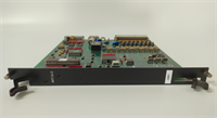
In the world of ABB 800xA systems, the IOR810 is the “muscle” of the S800 I/O rack. While other modules handle delicate 4-20mA signals or fast digital comms, the IOR810 is built to take a beating. It’s the module I specify when I need to drive a 230V AC motor starter coil directly from the controller, eliminating the need for a separate cabinet full of interposing relays. This saves space, wiring time, and potential failure points. I’ve seen these modules cycling huge solenoid valves in petrochemical plants for over a decade, still clicking away reliably despite the heat and vibration.
The key advantage here is the robustness of the electromechanical relay inside. Unlike solid-state outputs that can be fried by a voltage spike or leak current when “off,” the IOR810 provides true galvanic isolation and a hard break in the circuit. The Form C contact configuration gives you flexibility: wire it Normally Open for standard logic, or Normally Closed for fail-safe applications (though remember, a power loss to the module won’t de-energize a NC wired load unless you use a monitored safety circuit). One thing to watch: because these are mechanical relays, they have a finite life. If you’re switching a chattering valve 10 times a second, you’ll burn these out in months. Use them for on/off control, not PWM.
Quality SOP & Tech Pitfalls (The Reality Check)
The Lab Report (SOP)
We treat relay modules differently than electronics. First, we visually inspect the terminal block for signs of arcing or heat discoloration—a telltale sign of overloaded past usage. Then, we mount the IOR810 on a live S800 test rack with an AC 800M controller. We cycle each of the 8 channels 50 times under a rated resistive load (2A @ 230V AC) while monitoring contact resistance with a milliohm meter. We verify the LED indication matches the physical state. We also perform a dielectric strength test (Hi-Pot) at 1500V AC for 1 minute to ensure isolation integrity. Finally, we log the serial number and seal it in anti-static packaging. We use a Fluke 179 for load testing to ensure accurate current measurement.
We treat relay modules differently than electronics. First, we visually inspect the terminal block for signs of arcing or heat discoloration—a telltale sign of overloaded past usage. Then, we mount the IOR810 on a live S800 test rack with an AC 800M controller. We cycle each of the 8 channels 50 times under a rated resistive load (2A @ 230V AC) while monitoring contact resistance with a milliohm meter. We verify the LED indication matches the physical state. We also perform a dielectric strength test (Hi-Pot) at 1500V AC for 1 minute to ensure isolation integrity. Finally, we log the serial number and seal it in anti-static packaging. We use a Fluke 179 for load testing to ensure accurate current measurement.
The Engineer’s Warning (Pitfalls)
The biggest killer of the IOR810 is inductive kickback. If you switch a DC solenoid or a large AC contactor without a proper snubber circuit (RC network or flyback diode) across the load, the arc generated when the relay opens can weld the contacts shut or pit them so badly they fail to make contact next time. I’ve seen entire racks fail because one channel welded shut, keeping a dangerous process running. Always install suppression components on inductive loads. Another pitfall is current derating. The datasheet says 2A, but that’s for resistive loads. For inductive loads (AC-15 category), you must derate to roughly 0.5A–0.8A. Exceeding this drastically shortens the relay life. Don’t trust the “2A” label blindly for motor loads.
The biggest killer of the IOR810 is inductive kickback. If you switch a DC solenoid or a large AC contactor without a proper snubber circuit (RC network or flyback diode) across the load, the arc generated when the relay opens can weld the contacts shut or pit them so badly they fail to make contact next time. I’ve seen entire racks fail because one channel welded shut, keeping a dangerous process running. Always install suppression components on inductive loads. Another pitfall is current derating. The datasheet says 2A, but that’s for resistive loads. For inductive loads (AC-15 category), you must derate to roughly 0.5A–0.8A. Exceeding this drastically shortens the relay life. Don’t trust the “2A” label blindly for motor loads.
Installation & Configuration Guide
Phase 1: Pre-Installation
⚠️ ISOLATE LOAD POWER. Turn off the 24V DC or 230V AC supply feeding the field devices. Lockout/Tagout (LOTO) is mandatory.
⚠️ CHECK BASEPLATE. Ensure the S800 baseplate (e.g., TU810) is securely mounted and the bus connectors are clean. Verify the addressing dip switches on the baseplate match your project configuration.
Phase 2: Removal
Disconnect field wiring from the removable terminal block. If the terminals are tight, use a small flathead screwdriver to gently release the cage clamp; do not pull the wire violently. Unlock the module from the baseplate using the release latch at the top or bottom. Slide the IOR810 out horizontally.
Disconnect field wiring from the removable terminal block. If the terminals are tight, use a small flathead screwdriver to gently release the cage clamp; do not pull the wire violently. Unlock the module from the baseplate using the release latch at the top or bottom. Slide the IOR810 out horizontally.
Phase 3: Installation
Align the new IOR810 with the baseplate guides and slide it in firmly until it clicks and the bus connector engages. Lock the retention latch. Reconnect field wiring to the terminal block. Crucial: Ensure wire ferrules are used for stranded wire to prevent fraying and poor contact. Tighten terminal screws to 0.5–0.6 Nm torque. If switching inductive loads, install RC snubbers or flyback diodes directly at the terminal block or on the load side.
Align the new IOR810 with the baseplate guides and slide it in firmly until it clicks and the bus connector engages. Lock the retention latch. Reconnect field wiring to the terminal block. Crucial: Ensure wire ferrules are used for stranded wire to prevent fraying and poor contact. Tighten terminal screws to 0.5–0.6 Nm torque. If switching inductive loads, install RC snubbers or flyback diodes directly at the terminal block or on the load side.
Phase 4: Power-On & Testing
Restore logic power to the S800 rack (24V DC to the baseplate). The module status LED should turn green (or no fault). Restore load power. Force an output “ON” from the controller (Control Builder / 800xA). Verify the red channel LED lights up and listen for the distinct “click” of the relay. Measure voltage at the load to confirm switching. Repeat for all channels. Monitor for any abnormal heating after 15 minutes of operation.
Restore logic power to the S800 rack (24V DC to the baseplate). The module status LED should turn green (or no fault). Restore load power. Force an output “ON” from the controller (Control Builder / 800xA). Verify the red channel LED lights up and listen for the distinct “click” of the relay. Measure voltage at the load to confirm switching. Repeat for all channels. Monitor for any abnormal heating after 15 minutes of operation.
IOR810 ABB
Compatible Replacement Models
- ✅ Drop-in Replacement: IOR810 (3BSE017962R1) – The standard model. Any revision (R1, R2, etc.) is generally interchangeable physically and functionally.
- ⚠️ Alternative (Higher Density): IOD810 – This is an 8-channel solid-state digital output (24V DC only). It fits the same baseplate but cannot switch AC loads and has different wiring requirements. Do not substitute unless your loads are exclusively 24V DC and you understand the leakage current implications.
- ❌ Not Compatible: IOR808 – Older or different density relay module with different pinouts or baseplate requirements. Verify baseplate compatibility before attempting installation.
Frequently Asked Questions (FAQ)
What is the difference between IOR810 and IOD810?
The IOR810 uses electromechanical relays and can switch both AC (up to 230V) and DC loads with high isolation. The IOD810 uses solid-state transistors, can only switch 24V DC, is faster, has infinite life, but leaks a small current when off and cannot handle AC. Choose IOR810 for versatility and true isolation; choose IOD810 for high-speed DC switching.
The IOR810 uses electromechanical relays and can switch both AC (up to 230V) and DC loads with high isolation. The IOD810 uses solid-state transistors, can only switch 24V DC, is faster, has infinite life, but leaks a small current when off and cannot handle AC. Choose IOR810 for versatility and true isolation; choose IOD810 for high-speed DC switching.
Can I use the IOR810 for safety-critical emergency stops?
Generally, no, not as a single point of failure. While the relay provides isolation, the IOR810 is not a certified safety module (SIL2/SIL3) on its own. For E-Stop circuits, you should use a dedicated safety I/O module (like the S800 Safety series) or a hardwired safety relay circuit that monitors the output. Relying on a standard PLC output for safety is a violation of most safety standards.
Generally, no, not as a single point of failure. While the relay provides isolation, the IOR810 is not a certified safety module (SIL2/SIL3) on its own. For E-Stop circuits, you should use a dedicated safety I/O module (like the S800 Safety series) or a hardwired safety relay circuit that monitors the output. Relying on a standard PLC output for safety is a violation of most safety standards.
My relay contacts are welding shut. Why?
This is almost always due to inrush current or inductive kickback. If you are switching a large contactor coil or a capacitive load, the initial surge exceeds the 2A rating, causing an arc that welds the contacts. Install a snubber circuit (RC for AC, Diode for DC) across the load terminals to suppress the arc. Also, verify you aren’t exceeding the AC-15 derated current limit.
This is almost always due to inrush current or inductive kickback. If you are switching a large contactor coil or a capacitive load, the initial surge exceeds the 2A rating, causing an arc that welds the contacts. Install a snubber circuit (RC for AC, Diode for DC) across the load terminals to suppress the arc. Also, verify you aren’t exceeding the AC-15 derated current limit.
How do I know if the module is faulty?
If the controller commands an output ON, the red LED lights up, but the load doesn’t energize (and load power is present), the relay contacts may be pitted or open. Conversely, if the output is commanded OFF but the load stays energized, the contacts are likely welded shut. You can measure continuity across the NO/COM terminals with power off to verify. If the module fails to communicate with the baseplate (green status LED off/flashing red), the internal bus interface may be damaged.
If the controller commands an output ON, the red LED lights up, but the load doesn’t energize (and load power is present), the relay contacts may be pitted or open. Conversely, if the output is commanded OFF but the load stays energized, the contacts are likely welded shut. You can measure continuity across the NO/COM terminals with power off to verify. If the module fails to communicate with the baseplate (green status LED off/flashing red), the internal bus interface may be damaged.
Does the IOR810 require an external 24V supply for its own logic?
No. The IOR810 draws its logic power directly from the S800 backplane bus (provided by the power supply unit feeding the baseplate, e.g., TP810). You only need to provide external power for the loads connected to the relay contacts.
No. The IOR810 draws its logic power directly from the S800 backplane bus (provided by the power supply unit feeding the baseplate, e.g., TP810). You only need to provide external power for the loads connected to the relay contacts.