 Tel:
Tel:  Email:
  WhatsApp:
 Description
Key Technical Specifications
- Number of Channels: 4 independent analog outputs
- Output Signal: 4-20mA (Current sourcing)
- Resolution: 12-bit + sign (approx. 0.025% of range)
- Load Impedance: Max 600Ω (at 24V supply), typically 0-500Ω recommended
- Accuracy: ±0.1% of full scale at 25°C
- Conversion Time: < 2ms per channel (typical)
- Isolation: Galvanic isolation between field side and logic bus (500V AC test voltage)
- Diagnostics: Wire break detection (open loop), under-range/over-range flags
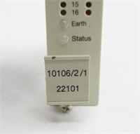
- Status Indication: Green LED for module status, Red/Green LEDs per channel for activity/fault
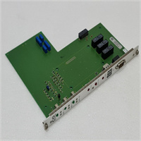
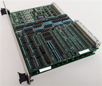
- Mounting: DIN rail mount on S800 baseplate (TU810, TU811, TU812, etc.)
- Power Supply: Powered via internal S800 bus (no external 24V logic supply needed for the module itself)
- External Power: Requires external 24V DC supply for the current loop (depending on wiring configuration: 2-wire vs 4-wire)
Product Introduction
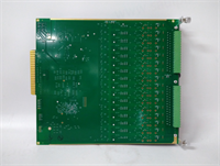
The ABB IOP310 is the go-to solution when you need to tell a valve exactly how far to open or a drive exactly how fast to spin. In the S800 architecture, this module sits right next to the controller, converting digital commands into robust 4-20mA signals that can travel hundreds of feet to the field without losing integrity. I’ve used these in everything from oil refineries to pulp mills; they are workhorses. Unlike cheaper generic analog cards, the IOP310 has built-in diagnostics that can detect a broken wire before it causes a process upset—critical when you’re controlling a steam valve that needs to fail-safe.The “SAC” suffix you mentioned is unusual for standard ABB stock. If this is a legacy part from a specific machine builder (e.g., a Sacmi tile press or a specialized SAC pump control panel), the core electronics are likely standard IOP310, but the firmware or labeling might be customized. Always double-check the wiring diagram if “SAC” is printed on the label, as custom variants sometimes swap pin assignments for common terminals. However, for 99% of replacements, a standard IOP310 (3BSE017963R1) will slide right into the baseplate and work immediately with your AC 800M controller.
Quality SOP & Tech Pitfalls (The Reality Check)
The Lab Report (SOP)
We verify analog precision rigorously. First, visual inspection for burnt components or corroded terminals. Then, we mount the IOP310 on a test rack and connect a calibrated Fluke 754 Process Calibrator to each channel. We command 4mA, 12mA, and 20mA from the controller and measure the actual output. We check for linearity errors exceeding ±0.1%. We also simulate a wire break by disconnecting the load to ensure the module raises the “Wire Break” alarm in the controller within 1 second. Finally, we check the isolation resistance between the bus and field terminals.The Engineer’s Warning (Pitfalls)
The most common headache with the IOP310 is ground loops and power supply configuration.
- Ground Loops: If you ground the shield at both the cabinet and the field device, and there’s a potential difference, you’ll see a “wandering” 4-20mA signal that makes control valves hunt. Ground shields at one end only (usually the cabinet side).
- Loop Power: The IOP310 does not supply power to the loop internally (unlike some input modules). You must provide an external 24V DC supply for the 4-20mA loop. If you forget this, you’ll get 0mA output regardless of the command.
- Load Limit: Don’t try to drive a high-impedance load (>600Ω) without checking your supply voltage. If the loop resistance is too high, the module can’t push 20mA, and your valve won’t reach 100% open.
Installation & Configuration Guide
Phase 1: Pre-Installation
⚠️ ISOLATE POWER. Turn off the 24V DC supply to the S800 rack and the external loop power supply.
⚠️ CHECK BASEPLATE. Ensure the baseplate (e.g., TU810) is clean and the bus connectors are not bent. Verify the address switches on the baseplate match the hardware configuration in Control Builder.Phase 2: Removal
Disconnect field wiring from the removable terminal block. Use a small screwdriver to release the cage clamps gently. Unlock the module from the baseplate using the retention latch. Slide the IOP310 out horizontally.Phase 3: Installation
Slide the new IOP310 into the baseplate until it clicks and the bus connector engages. Lock the latch. Reconnect field wiring. Crucial: Ensure you are wiring the external 24V loop power correctly (typically Terminal 1 or 2 depending on the specific baseplate wiring diagram, often shared across the terminal block). Use ferrules for stranded wires.Phase 4: Power-On & Testing
Restore power. The green “Module Status” LED should be solid. In Control Builder / 800xA, monitor the output values. Force a 50% output (12mA) and measure with a multimeter in series with the loop. Verify the reading is within tolerance (11.98–12.02mA). Test the wire-break diagnostic by momentarily disconnecting a wire; the system should alarm.
IOP310 SAC
Compatible Replacement Models
- ✅ Drop-in Replacement: IOP310 (3BSE017963R1) – The standard model. Revisions (R1, R2) are interchangeable.
- ⚠️ Alternative (Voltage Output): IOP330 – This is a 0-10V / 0-20V analog output module. It fits the same baseplate but outputs voltage, not current. Do not substitute unless your field devices accept voltage signals and you reconfigure the project.
- ❌ Not Compatible: IOP300 – This is an Analog Input module (4-20mA Input). It looks similar but functions in reverse. Plugging this in will not give you output control.
Frequently Asked Questions (FAQ)
What does the “SAC” in “IOP310 SAC” mean?
“SAC” is not a standard ABB suffix for the IOP310. It likely refers to:
- A specific System Integrator or OEM (e.g., a machine builder named SAC) who applied their own label.
- A misreading of “S800” (the series name).
- A custom firmware version for a specific application.
Recommendation: Treat it as a standard IOP310 for replacement purposes, but verify the wiring diagram against your specific machine drawings to ensure no custom pin swaps were made.
Can the IOP310 drive 3-wire transmitters?
The IOP310 is a current sourcing output. It drives 2-wire loads (where the load is passive) or 4-wire actuators (where the actuator has its own power and accepts a current reference). It cannot “power” a 3-wire transmitter in the way an input module powers a 2-wire sensor. You must provide external power for the actuator if it requires it.Why is my output reading 0mA even though the controller says 50%?
- Check if the external 24V loop power is connected and active. The IOP310 needs this to drive the current.
- Check for open circuits (broken wires) in the field wiring.
- Verify the load impedance isn’t too high (>600Ω).
- Check the module status LED; if it’s red, the module may be faulty or not configured correctly in the hardware tree.
Is the IOP310 hot-swappable?
Yes, the S800 system supports hot-swapping of I/O modules if the system is configured for it and the baseplate remains powered. However, removing an analog output module will cause the output to go to 0mA (or last held value depending on configuration), which could trip a process. Always force outputs to a safe state before swapping.How do I configure the wire-break detection?
Wire-break detection is enabled in the Control Builder hardware configuration for the specific channel. You can set the reaction to “Alarm Only” or “Alarm + Hold Last Value.” Ensure the threshold settings match your process requirements.