 Tel:
Tel:  Email:
  WhatsApp:
 Description
Product Introduction
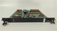
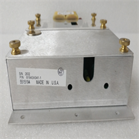
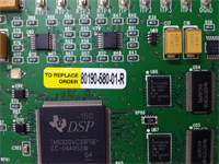
The heartbeat of any ABB INFI 90 control rack is the IEPAS02 power supply. While the intelligent modules process the logic, the IEPAS02 ensures they have the clean, stable voltage required to operate. In plants running these systems for 20+ years, electrolytic capacitors inside the original power supplies eventually dry out, leading to voltage ripple that causes erratic I/O behavior, communication drops, or total node failure.We recently supplied a batch of IEPAS02 units to a coal-fired power station where a single failing power supply was causing intermittent “Bad Quality” flags on critical temperature inputs. Replacing the IEPAS02 eliminated the noise on the backplane instantly. Unlike generic industrial power supplies, the IEPAS02 features a proprietary form factor that slides directly into the INFI 90 immersion rack, mating with the backplane bus bars without external wiring for the output. To be frank, attempting to rig a generic DIN-rail power supply to feed an INFI 90 backplane is dangerous and unreliable; the IEPAS02 is engineered to handle the specific inrush currents and load steps of the immersion modules.
Key Technical Specifications
| Parameter | Value |
|---|---|
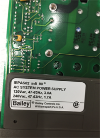
| Part Number | IEPAS02 (Supersedes older revisions like IEPAS01) |
| System Compatibility | ABB Bailey INFI 90, Symphony Plus (Legacy Nodes) |
| Input Voltage | 85 – 264 VAC (47-63 Hz) OR 90 – 300 VDC (Universal Input) |
| Output Voltage | +5VDC (Logic), ±15VDC (Analog/Comm) via Backplane |
| Power Rating | Typically 60W – 100W (Dependent on specific load config) |
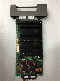
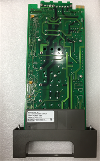
| Mounting | “Immersion” Slide-in Style (Fits INFI 90 Chassis) |
| Redundancy | Supports N+1 Redundancy when paired with diode OR-ing modules |
| Indicators | AC OK, DC OK, Fault LEDs |
| Protection | Over-voltage, Over-current, Short-circuit, Thermal shutdown |
| Operating Temperature | 0 °C to +60 °C (Derated above 50°C) |
| Dimensions | Standard INFI 90 Immersion Footprint (approx. 3HP width) |
| Status | Obsolete / End of Life (EOL) – Limited Availability |
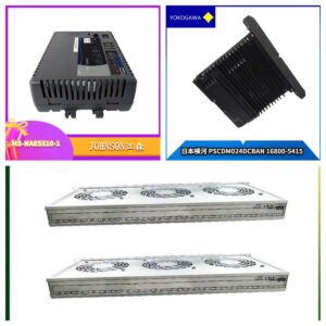
IEPAS02 ABB
Application Scenarios & Pain Points
A petrochemical refinery faced a crisis when their primary INFI 90 node controlling a distillation column began resetting randomly every few hours. The diagnostics pointed to a “Low Voltage” warning on the backplane. The culprit was an aging IEPAS02 that could no longer hold regulation during the brief inrush current when a relay module activated. Swapping in a new IEPAS02 restored stable voltage levels, ending the random resets. This module is vital because it isolates the sensitive DCS electronics from the noisy, fluctuating plant power grid.
- Power Generation (Boiler/Turbine): Need reliable power for flame scanner amplifiers and turbine vibration monitors? The IEPAS02 provides the clean ±15V analog rails these sensitive cards require.
- Pulp & Paper Digesters: What if your plant power experiences frequent sags or surges? The wide input range (85-264VAC) of the IEPAS02 allows it to ride through minor grid disturbances without dropping the control node.
- Water/Wastewater Treatment: Remote pump stations often have “dirty” power. The IEPAS02’s robust filtering prevents conducted noise from corrupting serial communication between the node manager and I/O modules.
- Steel Mill Reheat Furnaces: High ambient temperatures accelerate power supply aging. Proactive replacement of IEPAS02 units in hot zones prevents unexpected furnace control loss.
Case Study:
A large municipal water authority operates 10 pumping stations controlled by ABB INFI 90 systems installed in the mid-1990s. Over two years, they experienced three separate incidents where entire nodes went offline due to power supply failures. Each outage required an emergency technician dispatch and resulted in temporary loss of remote monitoring. The chief engineer decided to proactively replace all IEPAS02 units across all 10 sites during scheduled maintenance windows. They purchased a bulk lot of refurbished-but-tested IEPAS02 units. The swap took 20 minutes per station (hot-swap capable in redundant setups). Since the replacement program, zero power-supply-related node failures have occurred in 4 years. The cost of the proactive replacement was less than 10% of the cost of a single emergency overtime call-out plus potential environmental fines from a pump failure.Lessons Learned: Installation Pitfalls
- Inrush Current & Breaker Tripping — When inserting a new IEPAS02 into a live backplane (even in redundant systems), the charging of internal capacitors can cause a momentary high inrush current. ❗ If the branch circuit breaker is old or sized too tightly, this can trip the breaker, taking down the entire rack (including the redundant partner). Always ensure the branch breaker has a “D” or “K” curve (slow blow) suitable for switching power supplies.
- Redundancy Diode Module Dependency — The IEPAS02 itself does not perform the OR-ing function for redundancy; it relies on a separate Diode Termination Module (often located at the end of the rack or integrated into the backplane assembly). If you replace a power supply but the diode module is faulty, the system will not actually be redundant, and a fault on one supply could back-feed and kill the other. Always test the redundancy by pulling the active supply after installation to confirm the second takes over seamlessly.
- Input Voltage Selection (Jumpers) — While many modern IEPAS02 units are auto-ranging, some older revisions or specific batches may have jumpers or switches for 115V vs 230V input. Setting this incorrectly to 115V while connecting to 230V will result in immediate catastrophic failure (smoke/explosion). Verify the label and jumper settings before applying power.
- Backplane Pin Alignment — Similar to the I/O modules, the power supply has heavy-duty pins for current delivery. Forcing the unit in at an angle can bend these pins, leading to high-resistance connections. This causes voltage drops under load and localized heating, which can melt the connector housing over time. Insert straight and firm.
- Load Balancing in Redundant Pairs — In a redundant setup, both power supplies should share the load roughly equally. If one unit is carrying 90% of the load and the other 10%, it indicates a mismatch in output voltage calibration or a failing unit. Use a multimeter to check the output voltage of both units; they should be within millivolts of each other.