
 Tel:
Tel:  Email:
  WhatsApp:
 Description
Key Technical Specifications
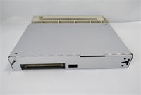
- Part Number: YB560103-AL
- Designation: DSQC 209
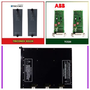
- Compatible Controllers: ABB S4C, S4C Plus
- Input Voltage: 24 V DC (+/- 10%)
- Digital Inputs: 16 channels (24V DC, sinking/sourcing configurable)
- Digital Outputs: 16 channels (24V DC, 0.5A per channel max)
- Analog I/O: Optional expansion via daughter cards (base unit is primarily digital)
- Communication Bus: Internal S4C Backplane (not directly Ethernet)
- Connector Type: AMP or Phoenix Contact (depending on revision)
- Protection Class: IP20 (Must be installed inside control cabinet)
- Operating Temperature: 0°C to +55°C (32°F to 131°F)
- Storage Temperature: -20°C to +70°C
- Dimensions: Approx. 160mm x 100mm x 40mm (Eurocard form factor)
- Weight: Approx. 0.4 kg
Product Introduction
If you’ve ever been called to a car plant at 2 AM because a spot welder stopped moving, you know the S4C controller. It’s the tank of robot controllers—bulky, loud, and indestructible. The DSQC 209 (YB560103-AL) is the brain’s nervous system in that box. It doesn’t do the complex path calculations; the CPU board does that. This board just makes sure that when the CPU says “clamp,” the pneumatic valve actually opens. I’ve seen these boards coated in thick layers of metallic dust from grinding operations, still blinking green after ten years.The reason maintenance teams hoard these is simplicity. There’s no OS to crash, no Windows update to brick it. It’s hard-wired logic mapped to memory addresses. The YB560103-AL revision specifically fixed some noise immunity issues found in earlier “-AK” versions, making it less prone to false trips when big contactors slam nearby. However, don’t expect miracles. If your 24V DC supply dips below 20V during a heavy load start, this board will reset, and the robot will fault out. It needs clean power. That’s the only weakness in an otherwise bulletproof design.
 Quality SOP & Tech Pitfalls (The Reality Check)
 Quality SOP & Tech Pitfalls (The Reality Check)
The Lab Report (SOP)
We don’t just plug it in and hope. First, we inspect the backplane pins under magnification. Bent pins are the #1 cause of “ghost faults” in S4C systems. We check the electrolytic capacitors for bulging—a common age-related failure. Then, we mount the DSQC 209 into a live S4C test rack. We simulate all 16 inputs and verify the corresponding register bits flip in the controller memory within 10ms. We load-test the outputs with actual 24V relays, not just LEDs, to ensure the transistors can handle the current without voltage drop. Finally, we run a thermal cycle from 20°C to 50°C while toggling I/O to catch intermittent solder cracks.The Engineer’s Warning (Pitfalls)
Here is the trap: The S4C backplane is sensitive to static, but worse, it’s sensitive to sequence. I watched a technician swap this board while the controller was in “Motor On” state. The transient spike fried the backplane driver on the main CPU, turning a 500 board swap into a 15,000 CPU replacement. Always power down the entire controller. Another disaster zone: mixing up the ribbon cable orientation. The connectors look symmetric, but they aren’t. Forcing the cable in backwards reverses the 24V and Ground lines, instantly blowing the input fuses on the board. Check the red stripe on the ribbon cable. Always.
Installation & Configuration Guide
Phase 1: Pre-Installation
⚠️ POWER DOWN. Turn the main disconnect switch on the robot controller to OFF. Wait at least 2 minutes for the DC bus capacitors to discharge (verify with a multimeter on the DC link terminals). Take a photo of every cable connected to the old DSQC 209. Label the ribbon cables and terminal blocks. S4C modules rely on specific slot positions; note exactly which slot (e.g., Slot 3) this card occupies.Phase 2: Removal
Unscrew the two retaining screws at the top and bottom of the faceplate. Gently pull the module straight out. Do not wiggle it excessively; you might damage the backplane connector. If it sticks, check for hidden locking tabs. Disconnect the ribbon cable and terminal wiring from the old unit. Inspect the cabinet-side connectors for corrosion.Phase 3: Installation
CRITICAL: Verify the DIP switches or jumpers on the new DSQC 209 match the old one exactly. These often set the node address or termination resistance. If you miss this, the controller won’t see the I/O. Align the guide rails and slide the new module firmly into the slot until the backplane connector seats with a solid click. Reconnect the ribbon cable (ensure Pin 1 alignment). Re-attach terminal wires according to your photos. Tighten terminal screws to 0.5 Nm. Secure the faceplate screws.Phase 4: Power-On & Testing
Turn the main disconnect ON. Watch the LED sequence on the DSQC 209. You should see a brief flash of all LEDs, then the “Ready” or “Run” LED should stay solid green. If the “Fault” LED turns red, check the slot configuration in the robot’s system parameters (IOCFG). Force a few outputs from the teach pendant to verify physical action. Monitor the system for 15 minutes to ensure no intermittent communication errors appear in the event log.
Compatible Replacement Models
 Compatible Replacement Models
- ✅ Drop-in Replacement: ABB DSQC 209 YB560103-AM or -AN.
- Note: Later revisions (-AM, -AN) are backward compatible with the -AL. They often have improved component sourcing. No parameter changes needed.
- ⚠️ Software Compatible: ABB DSQC 220 / DSQC 230.
- Reason: These are newer I/O modules for S4CPlus that can sometimes replace the 209, but they may require a firmware update on the main CPU and a reconfiguration of the I/O map in the system parameters. Expect 1-2 hours of engineering time.
- ❌ Hardware Mod Required: ABB IRC5 IO Boards (e.g., DSQC 651).
- Warning: These are for the newer IRC5 controllers. They physically fit in some racks but use a different communication protocol (DeviceNet/Profinet vs. S4C internal bus). Do not attempt to install these in an S4C controller. It will not work and could damage the backplane.
Frequently Asked Questions (FAQ)
Q: Can I swap this board while the robot is running production?
No. The S4C controller does not support hot-swapping I/O modules. Removing the board while powered will cause an immediate system fault, stop the robot mid-cycle (potentially dropping a part), and risks arcing the backplane contacts. Plan for a scheduled downtime window.Q: My replacement board has a different suffix (e.g., -AM instead of -AL). Will it work?
Yes. ABB frequently updates the suffix letter to denote minor component changes or supplier shifts. As long as the base number is DSQC 209 and the form factor is identical, the -AM, -AN, or -AO revisions are direct replacements for the -AL. The electrical characteristics remain the same.Q: The LED is flashing red/green alternately. What does that mean?
That usually indicates a configuration mismatch. The controller sees the hardware, but the software definition in the IOCFG file doesn’t match what the board expects (e.g., the system thinks it’s a 32-channel card, but it’s a 16-channel). Check your system parameters. It can also mean the board is seated poorly; reseat it firmly.Q: Is this board repairable if one output channel blows?
Technically, yes, a skilled technician can replace the output transistor array. Practically? No. The cost of labor and testing exceeds the price of a surplus replacement. Plus, if one channel blew due to a short, other components on the board might be stressed. Swap the whole unit. Keep the old one as a donor for emergency parts if you must.Q: How do I know if the problem is this board or the wiring outside?
Disconnect the external field wiring from the terminal block. Use a multimeter to check the resistance of the external load (solenoid/relay). If it’s shorted (near 0 ohms), your wiring or device is the problem, not the board. If the external wiring checks out, try forcing the output from the teach pendant. If the LED lights up but the device doesn’t move, check your 24V supply voltage at the terminal. If the LED doesn’t light up at all, the board is likely dead.Q: Does this come with a warranty?
Standard surplus items often come with a 30-day DOA (Dead on Arrival) warranty. Certified refurbished units from reputable suppliers usually carry a 1-year warranty. Given the critical nature of this part in a production line, insist on the 1-year option. A $200 savings isn’t worth the risk of another line stoppage next month.