 Tel:
Tel:  Email:
  WhatsApp:
 Description
Technical Specifications (For Spare Parts Verification)
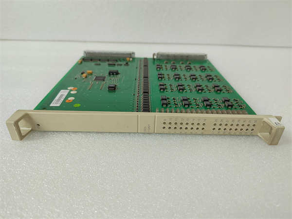
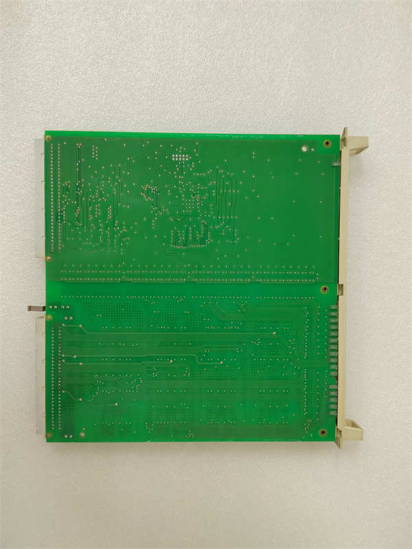
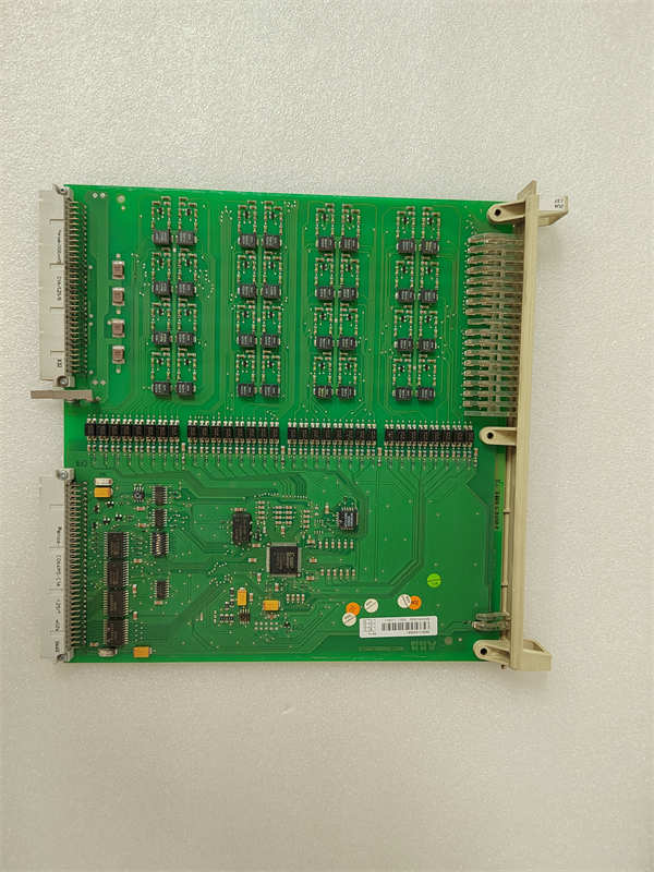
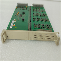
- Product Model: DSDI110AV1
- Manufacturer: ABB
- System Platform: AC 800M controller with S800 I/O in 800xA Distributed Control System
- Input Channels: 16 isolated digital inputs
- Input Voltage Range: 48–125 VDC (nominal 125 VDC), with defined ON/OFF thresholds per IEC 60255
- Input Type: Dry contact or wetted contact compatible; designed for direct connection to high-level DC control circuits
- Isolation: Reinforced isolation between field and logic circuits (tested to >2.5 kV)
- Backplane Interface: Mounts on TB801/TB802 terminal base; communicates via ModuleBus
- Diagnostic Features: Group fault indication, open-circuit detection, and per-channel LED status
- Operating Temperature: 0°C to +60°C
- Compliance: Designed for use in utility and heavy-industry applications with high electromagnetic interference
System Role and Downtime Impact
The DSDI110AV1 is specifically engineered for applications where field devices operate at elevated DC voltages—common in power generation (e.g., generator breaker status), transmission substations, and large turbine auxiliary systems. Unlike standard 24 VDC DI modules, it eliminates the need for external relays or signal conditioners by accepting 125 VDC directly. This simplifies wiring but places higher electrical stress on internal components.
In these environments, the module often feeds signals into critical protection or sequencing logic. If it fails—due to loss of input detection, communication dropout, or internal short—the control system may misinterpret equipment state. For example, a false “breaker open” signal could prevent synchronization, while a missed “turbine trip” signal might delay emergency response. Because such signals are typically non-redundant in legacy designs, a single DSDI110AV1 failure can trigger process shutdowns or compromise operational safety.
Reliability Analysis and Common Failure Modes
Operating continuously at high DC voltages accelerates component aging in the DSDI110AV1. The most common failure mechanisms include: degradation of high-voltage optocouplers due to prolonged electric field stress, carbon tracking on PCB surfaces in dusty/humid conditions, and failure of input filtering capacitors leading to noise susceptibility. The input circuitry is also vulnerable to voltage surges from switching transients in DC control panels—especially if surge suppression is absent upstream.
A key design constraint is thermal management: under full load (all 16 channels active at 125 VDC), internal power dissipation increases, which—combined with poor cabinet ventilation—can shorten component life. Additionally, the lack of per-channel diagnostics makes it difficult to isolate failing inputs without physical inspection.
Maintenance best practices include: verifying that input voltages remain within spec (avoiding sustained overvoltage), inspecting for discoloration or arcing near terminals, ensuring clean and dry I/O cabinets, and cross-checking field signal integrity during outages. Spares should be stored in low-humidity environments to prevent moisture ingress into high-impedance circuits.
DSDI110AV1 3BSE018295R1 ABB
Lifecycle Status and Migration Strategy
ABB has discontinued the DSDI110AV1 as part of its legacy S800 I/O rationalization. No new production exists, and factory repair services are unavailable. Continued operation depends on a shrinking pool of used or New Old Stock (NOS) units, many of which have been exposed to decades of electrical stress—raising concerns about latent failures.
Short-term risk mitigation involves sourcing only from vendors who perform high-voltage functional testing (including insulation resistance and input threshold validation) and maintaining at least one tested spare per critical system.
For long-term sustainability, ABB does not offer a direct 125 VDC replacement in its current portfolio. The recommended approach is signal-level adaptation: retain the existing high-voltage field wiring but install an external signal conditioning interface (e.g., ABB’s TU810-based relay isolator or third-party HV-to-LV converter) that steps down to 24 VDC, then connect to a modern, supported DI module such as the DSDI 156 (3BSE042246R1). While this adds a layer of hardware, it enables migration to a supportable I/O platform without rewiring field devices. In new builds or major retrofits, full replacement of the DC control voltage system to 24 VDC is increasingly common, aligning with global standardization trends and improving overall system reliability.