Tel:
Tel:  Email:
  WhatsApp:
 Description
Technical Specifications (For Spare Parts Verification)
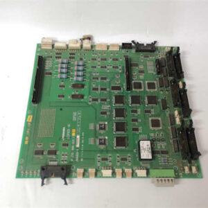
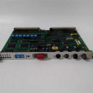
- Product Model: 2N3A8130-A
- Manufacturer: TOSHIBA (Industrial Components Division, historical)
- Type: Solid-State Relay (SSR) or DC Output Power Module
- Likely Output: DC (common in Japanese OEM designs of era), possibly 5–60 VDC range
- Estimated Load Current: 5–10 A (based on physical size and naming convention)
- Input Control Signal: Likely 5–24 VDC logic compatible
- Mounting: DIN rail or panel mount with screw terminals
- Isolation: Optical or transformer-based input-to-output isolation (typical for era)
- Indication: May include LED status indicator
- Cooling: Natural convection (no fan)
- Physical Dimensions: Approx. 80 x 60 x 40 mm (estimated from similar models)
- Terminal Type: Screw-clamp or spring-cage
System Role and Downtime Impact
The 2N3A8130-A typically resides inside OEM machinery control panels—such as those in legacy Toshiba, Komori, or Fuji-branded equipment—where it switches DC power to critical loads like electromagnetic brakes, heater bands, or pneumatic valve banks. Unlike modern modular I/O, these modules were often hardwired directly into custom control circuits with minimal redundancy. A failure results in an open or shorted output, causing either loss of actuation (e.g., a clamp won’t release) or unintended energization (e.g., a heater stays on). In high-uptime environments like semiconductor fabs or continuous web processing lines, this can halt production for hours or days while a replacement is sourced or reverse-engineered.
Reliability Analysis and Common Failure Modes
After 20–30 years of service, the 2N3A8130-A is prone to several age-related failure mechanisms:
- Output semiconductor degradation: Repeated thermal cycling fatigues the internal power transistor or thyristor, leading to increased on-resistance, overheating, or sudden open-circuit failure.
- Optocoupler aging: The input-side LED in the isolation circuit dims over time, reducing drive strength and causing intermittent switching at marginal control voltages.
- Solder joint fatigue: Thermal expansion mismatches between components and PCB cause micro-cracks, especially around high-current traces.
- Terminal corrosion: Moisture ingress or galvanic corrosion at screw terminals increases contact resistance, generating localized heat and voltage drop.
A key weakness is the lack of diagnostic feedback—most installations provide no indication of partial degradation until complete failure occurs. Additionally, many units were installed without adequate heatsinking, accelerating thermal wear.
Preventive maintenance should include:
- Thermographic inspection during operation to detect abnormal heating.
- Measuring voltage drop across output terminals under load (should be < 1 V).
- Verifying control signal integrity at the input pins during machine cycles.
- Keeping a known-good spare powered intermittently to prevent storage-related degradation.
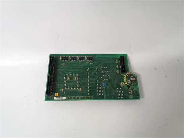
TOSHIBA 2N3A8130-A
Lifecycle Status and Migration Strategy
Toshiba no longer supports industrial control modules like the 2N3A8130-A, and original documentation is nearly impossible to obtain. Continuing to operate this component carries high risk due to zero manufacturer recourse and vanishing secondary supply.
As a temporary measure:
- Perform functional testing on any available spares using a bench power supply and dummy load.
- Consider retrofitting with a modern, pin-compatible SSR from brands like Omron, Panasonic, or Carlo Gavazzi—if electrical and mechanical fit can be confirmed.
- Document wiring and load characteristics to enable rapid substitution in an emergency.
For long-term sustainability, the optimal path is a targeted control panel modernization: replace the legacy module with a standard DIN-rail SSR paired with a fuse and status monitoring relay. This approach improves reliability, adds diagnostics, and uses globally available components. In machines with multiple obsolete parts, a full PLC retrofit may be justified to eliminate recurring obsolescence exposure.